
AD278A/AD279A PCI MUX Support Guide, June 2006


Peripheral Connections
RS-232 Asynchronous: DB-25
Appendix B
48
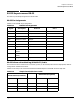
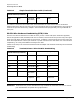
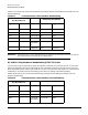
Table B-5 lists the pin-out connection between the DB25 adapter and the DB25 terminal/printer with
software or hardware handshaking.
IMPORTANT Some terminal or printer manufacturers may use different methods of flow control. Consult
your documentation for specific wiring requirements.
DB-25 Modem Cable
To connect a DB-25 equipped asynchronous adapter to a modem, use a standard straight-through cable. A
straight-through cable has a DB-25 female connector at the Digi end and a DB-25 male connector at the
modem end. All 25 pins are connected, 1 to 1, 2 to 2, 3 to 3 and so on. Use a shielded cable, and connect pin 1
of each connector to the cable shield.
Table B-5 Terminal/Printer Cable for Software (XON/XOFF) or Hardware (DTR)
Handshaking
DB-25 (Card End)
DB-25 Male
(Terminal/Printer)
Signal Pin Pin Signal
RTS 4 Connected to 5 CTS
GND Shell Connected to Shell GND
TxD 2 Connected to 3 RxD
RxD 3 Connected to 2 TxD
SG 7 Connected to 7 SG
CTS 5 Connected to 20 DTR
DTR 20 Connected to 8+6 DCD+DSR
DCD+DSR 8+6 Connected to 4 RTS