
AD278A/AD279A PCI MUX Support Guide, June 2006


Peripheral Connections
RS-232 Asynchronous: RJ-45
Appendix B
49
RS-232 Asynchronous: RJ-45
This section provides the pin diagram for RJ-45 cable.
RJ-45 Pin Assignments
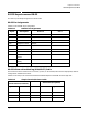
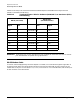
Table B-6 shows the pin diagram for RJ45 connector.
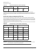
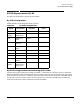
RJ45 8-Pin Plug Hardware Handshaking (DTR) Cable
Using an 8-pin plug, the cable wiring shown in Table B-7, is sufficient for a terminal, printer, or other DTE
devices configured for DTR (hardware) flow control. However, some terminals and printers may use a signal
other than DTR for flow control. In addition, some terminals and printers may have other cable requirements.
Consult your terminal or printer manual for this information. For universal compatibility, use the RJ-45
10-wire terminal/printer cable or a RoHS RJ-45 to DB-25 adapter.
Table B-6 RJ-45 Pin Assignments
Signal Description DTE Use Pin #
RI Ring Indicator Input 1
DSR
(DCD*)
Data Set
Ready (Data
Input 2
RTS Request to
Send
Output 3
GND Chassis
Ground
N/A 4
TXD Transmitted
Data
Output 5
RXD Received Data Input 6
SG Signal Ground Reference 7
CTS Clear to Send Input 8
DTR Data Terminal
Ready
Output 9
DCD
(DSR*)
Data Carrier
Detect (Data
Set Ready*)
Input 10