
HP AD278A and AD279A PCI Multiplexer Support Guide, Edition 2 - September 2006


Peripheral Connections
RS-232 Asynchronous: RJ-45
Appendix B
50
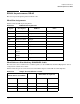
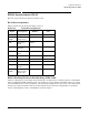
Table B-7 lists the pin-out conenction between the RJ45 8-pin adapter and the DB25 terminal/printer with
DTR handshaking.
IMPORTANT Some terminal or printer manufacturers may use different methods of flow control. Consult
your documentation for specific wiring requirements.
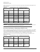
RJ-45 8-Pin Plug Hardware Handshaking (RTS/CTS) Cable
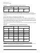
Using an 8-pin plug, the cable wiring shown in Table B-8 is sufficient for a terminal, printer, or other DTE
devices configured for RTS/CTS (hardware) flow control. However, some terminals and printers may have
other cable requirements. Consult your terminal or printer manual for this information. For more universal
compatibility, use the RJ-45 10-wire terminal/printer cable or a RoHS RJ-45 to DB-25 adapter.
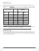
Table B-8 lists the pin-out connection between the RJ45 adapter and the DB-25 terminal/printer with
RTS/CTS handshaking.
Table B-7 Terminal/Printer C abl e with DTR Handshaking
RJ-45 (Card End)
DB-25 Male (Peripheral)
Signal Pin Pin Signal
TxD 4 Connected to 3 RxD
RxD 5 Connected to 2 TxD
CTS 7 Connected to 20 DTR
SG 6 Connected to 7 SG
GND 3 Connected
(via shield)
to
1 (or shell) GND
Jumpered 4+5 RTS+CTS
Table B-8 Terminal/Printer C abl e with RTS/CTS Han dshaking
RJ-45 (Card End)
DB-25 Male (Peripheral)
Signal Pin Pin Signal
DSR 1 Connected to 20 DTR
RTS 2 Connected to 5 CTS
GND 3 Connected
(via shield)
to
1 (or shell) GND