HP AD278A and AD279A PCI Multiplexer Support Guide HP-UX 11i v3 HP Part Number: AD278-9002D Published: November 2008 Edition: Edition 1
© Copyright 2008 Hewlett-Packard Development Company, L.P Legal Notices The information contained herein is subject to change without notice. The only warranties for HP products and services are set forth in the express warranty statements accompanying such products and services. Nothing herein should be construed as constituting an additional warranty. HP shall not be liable for technical or editorial errors or omissions contained herein. UNIX is a registered trademark of The Open Group.
Table of Contents About This Document.........................................................................................................7 Intended Audience.................................................................................................................................7 Document Organization.........................................................................................................................7 Typographic Conventions.....................................................
AD280A/AD281A Port Module Specifications.....................................................................................30 Cable Requirements and Specifications................................................................................................31 Physical Characteristics...................................................................................................................31 Grounding Requirements....................................................................................
List of Figures 1-1 1-2 1-3 1-4 1-5 1-6 2-1 2-2 2-3 2-4 2-5 2-6 2-7 2-8 2-9 2-10 2-11 2-12 2-13 2-14 2-15 2-16 AD278A PCI MUX 8-Port Adapter...............................................................................................10 AD279A PCI MUX 64-Port Adapter..............................................................................................10 RS-232 RJ45 Port Module...............................................................................................................
List of Tables 1 1-1 1-2 1-3 1-4 1-5 1-6 1-7 1-8 2-1 2-2 2-3 2-4 2-5 2-6 A-1 A-2 A-3 A-4 B-1 B-2 B-3 B-4 B-5 B-6 B-7 B-8 B-9 B-10 B-11 B-12 B-13 B-14 B-15 B-16 C-1 C-2 6 HP-UX 11i Releases.........................................................................................................................8 PCI MUX 8-Port Adapter AD278A Solution...................................................................................9 AD279A PCI MUX 64-Port Adapter Solution.....................................
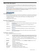
About This Document This document describes how to troubleshoot HP AD278A/AD279A PCI Multiplexer (MUX) serial adapters and peripherals. It also discusses technical specifications for the adapters and peripheral connections. Document updates may be issued between editions to correct errors or document product changes. To ensure that you receive the updated or new editions, you must subscribe to the appropriate product support service. See your HP sales representative for details.
Variable [] {} ... | The name of a variable that you can replace in a command or function or information in a display that represents several possible values. The contents are optional in formats and command descriptions. If the contents are a list separated by |, you can choose one of the items. The contents are required in formats and command descriptions. If the contents are a list separated by |, you can choose one of the items. The preceding element may be repeated an arbitrary number of times.
1 Introduction This chapter introduces the HP Peripheral Components Interconnect Multiplexer (PCI MUX) product. It also describes the components of HP AD278A/AD279A PCI MUX. This chapter addresses the following topics: • • • • “AD278A/AD279A PCI Multiplexer Components” (page 9) “AD278A/AD279A PCI MUX Adapters” (page 9) “Port Modules” (page 11) “Fan-Out Cable for AD278A PCI MUX 8-Port Adapter” (page 12) Overview HP AD278A/AD279A PCI MUX is a high-speed serial communication multiple port product.
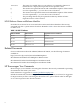
Table 1-5 HP PCI MUX Adapter Types Product Number Description Interface Maximum Port Card Type Speed and Speed Bus Voltage Number of Ports AD278A HP AD278A PCI MUX 8-port serial adapter Fan-Out Cable 115.2 kbps PCI 33MHz 3.3 V and 5.0 V 8 AD279A HP AD279A PCI MUX 64-port serial adapter Port Modules 38.640 kbps PCI 33MHz 3.3 V and 5.0 V 16 to 64 Every AD278A/AD279A PCI MUX adapter card has processors that control the flow of data through multiple communication ports.
Port Modules A port module is an interface between the AD279A PCI MUX 64-port adapter and the RS-232 peripheral device. Table 1-6 lists the port modules that can be connected to the AD279A PCI MUX 64-port adapter.
Figure 1-4 RS-232 DB25 Port Module Table 1-8 lists the metrics equivalent. Table 1-8 Metrics Equivalent Inches Centimetre 4.2 10.668 Fan-Out Cable for AD278A PCI MUX 8-Port Adapter A fan-out cable is an interface between AD278A PCI MUX 8-port adapter and RS-232 peripheral devices. The fan-out cable has a DB78 connector at one end. This end is connected to the AD278A PCI MUX 8-port adapter. The other eight ends of the cable have DB25 male connectors.
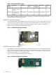
Figure 1-6 Power Supply NOTE: Third and fourth port modules require a seperate power supply.
2 Troubleshooting This chapter describes how to use the pmux_diag diagnostic utility. It also describes how to troubleshoot the terminal, printers, and modem installation problems after the ports are configured and enabled.
1. 2. Select Quit on the main menu. Press Enter. Driver Status Menu Selections The Driver Status drop down menu displays the following selections: • • • • Driver Status Board Status Counters Topology Figure 2-1 shows the Driver Status selection. Figure 2-1 pmux_diag utility Driver Status main menu NOTE: The pmux_diag utility version number is of the form B.x.xxxx Where: x - represents the release number, for example, 11.31.
Figure 2-2 Driver Status Display Board Status The Board (card) Status sub-menu enables you to view card specific information such as the card type, buffer block starting location, buffer size, and bus slot location. To view the card specific information, select Board Status sub-menu and press Enter. Information about additional boards, if any, is also displayed. Figure 2-3 shows the Board Status Display.
Figure 2-4 Select Port Group Display Highlight the desired group (for example, ports a1 through a16) and press Enter. Up to sixteen ports are displayed at a time. Figure 2-5 displays port group communication. Figure 2-5 Selected Group Communications Monitor Display Topology The Topology sub-menu allows you to troubleshoot problems related to the host cable. To view the host adapter card and port modules attached to it, select Topology sub-menu and press Enter.
Figure 2-6 Topology Display Port Status Menu Selections The second menu selection on the main menu is Port Status. The Port Status drop down menu displays the following selections: • • • • Breakout Box Data Scope Termio Register Dump Breakout Box The Breakout Box sub-menu allows you to do real time monitoring of data and control signal leads, calculated received and transmitted rates and cumulative bi-directional character counts. Figure 2-7 shows the port name of the selected device.
Press Enter or use the arrow key to select Data Scope. The lead status for the selected port is displayed. Figure 2-8 shows lead status for the selected port. Figure 2-8 Breakout Box Display This selection displays the RS-232 lead status. You can check for modem CD problems as well as the status of output flow-control. Additionally, transmit rate, receive rate, total characters received, total characters transmitted and buffered data counters are also displayed.
Figure 2-9 Data Scope Parameter Setup Display After the data capture parameters are setup, go to Start Scope or Review Data and press Enter. The data monitor screen is displayed. Figure 2-10 shows the Data Scope Monitor display. Figure 2-10 Data Scope Data Monitor Display The Data Scope Monitor screen shows the actual characters as they are being sent and/or received by the device. This screen displays both hexadecimal and ASCII data. Press any key and the Data Scope Capture Data screen is displayed.
Figure 2-11 Data Scope Capture Data Display The data can be captured and saved for later review. The default file name for input data is /tmp/emux.in and the default file name for output data is /tmp/emux.out. If desired, the data scope can be configured to run continuously. You can specify if you want to view the received data, send data or both. Termio The Termino sub-menu allows you to view general terminal interface data associated with the port.
NOTE: By default, the window content is saved in /tmp/profile Figure 2-13 shows the Register Dump details. Figure 2-13 Register Dump Display Diagnostics Menu Selections The Diagnostics menu seletion enables the user to perform the following tests: • • Loopback Send Loopback The loopback test is designed to test the primary components of the adapter cards and their functionality. The test can be run on a single port or a group of ports at the same time.
Figure 2-14 Diagnostics Loopback Test Send The Send sub-menu allows you to send a barber pole pattern to the selected port. It writes all printable alphanumeric characters out of a port. This test is useful when adding a new device and when a continuous stream of data is required to resolve wiring issues. The port configuration is 8 data bits, 1 stop bit and no parity. To view the data transmission details, highlight Send and press Enter. The number of transmitted characters is displayed.
Figure 2-16 Quit pmux_diag utility program Display Excessive Frequent getty Spawning You may encounter the following problem: Table 2-2 Excessive Frequent getty Spawning Problem Cause The following message appears on the console: This message usually indicates that the Reset the internal retry time to its initial incoming CD signal connected to a value or disable the port and then re-enable modem control port with CLOCAL set it. keeps toggling.
Table 2-3 Terminal Login Problems Problems Causes Action • No login prompt • Garbled message • Problems logging in These problems can occur because of any of the following reasons: • Port is not enabled • Port is set for wrong speed, parity, character size and so on. • Cabling problem • Hardware problem Perform one of the following actions: Verify whether the proper getty def entry is selected for the port in the /etc/inittab file.
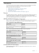
Connecting a Modem To connect a modem to your system, complete the following steps: 1. Edit the /usr/lib/uucp/Devices file. For example, for a Hayes compatible 2400 baud modem (where 1a16 is the port where the modem is located), add the following entry in the /usr/lib/uucp/Devices file: ACU cul1a16 2400 hayes 2. 3. 4. Verify whether the serial port is working properly by testing it with a terminal.
Troubleshooting Modem Table 2-5 lists the common modem error messages, their causes, and describes how to troubleshoot modem connections. Table 2-5 Modem Error Messages Error Messages Causes Actions NO DEVICES AVAILABLE The /usr/lib/uucp/devices file is not setup correctly. Edit /usr/lib/uucp/devices to include an entry for the /dev/culnpp file created earlier.
A Technical Specifications This appendix provides specification details for AD278A PCI MUX 8-port serial adapter, AD279A PCI MUX 64-port serial adapter, port modules, and cables. This appendix addresses the following topics: “Card Specifications” (page 29). “AD280A/AD281A Port Module Specifications” (page 30). “Cable Requirements and Specifications” (page 31). Card Specifications This section provides specification details for AD278A PCI MUX 8-port serial adapter and AD279A PCI MUX 64-port serial adapter.
HP AD279A PCI MUX 64-port Serial Adapter Specifications Table A-2 lists AD279A PCI MUX 64-port serial adapter specifications. Table A-2 AD279A PCI MUX 64-port Serial Adapter Specifications Power Requirements +5 V +/- 5% 0.43 amps typical plus module power draw Vio at +5 V 20 milliamps Card Type and Speed PCI 33MHz Environmental Requirements Ambient Temperature 10 to 55 degrees C Relative Humidity 5% to 90% Air Movement 30 CFM forced Altitude 0 to 12,000 feet (365.
Serial Interface Surge Suppression Threshold Voltage 13 V Response Time < 10 nS Mechanical Requirements RJ-45 (AD280A) Model DB-25 (AD281A) Model Length 12 inches (30.480 cm) 12 inches (30.480 cm) Width 7 inches (17.780 cm) 7 inches (17.780 cm) Height 2.25 inches (5.715 cm) 4.2 inches (10.668 cm) Weight 2 Pounds (907.20 gram) 4 Pounds (1814.40 gram) Cable Requirements and Specifications This section specifies cable characteristics and requirements.
NOTE: Not all RoHS products support all of the data rates listed below. Table A-4 Data Rate Versus Cable Length Data Rate (bps) Maximum Cable Length 57,600 or less 100 feet (3048.000 cm) 115,200 80 feet (2438.400 cm) 230,400 40 feet (1219.200 cm) 460,800 20 feet (609.600 cm) 921,600 10 feet (304.800 cm) The maximum length is the length of the cable from the adapter that is connected to a HP supplied interconnect device, such as a fan-out cable.
B Peripheral Connections This appendix provides the pin-out tables to connect the communication ports to the peripheral devices. The peripheral devices must be RS-232 compliant.This appendix addresses the following topics: • “RS-232 Asynchronous: DB-25” (page 33) • “RS-232 Asynchronous: RJ-45” (page 35) • “Cabling Pin-outs for HP Proprietory RJ45 and DB25 Devices” (page 38) RS-232 Asynchronous: DB-25 This section provides pin diagrams for a DB-25 cable.
This cable is a three-wire null modem cable. Transmitted data on one end of the cable is connected to Received data at the other end, and vice versa. The male DB-25 end can be plugged directly into most serial terminals and printers without any adapters. The female DB-25 end plugs directly into any RoHS DB-25 serial port.
Table B-4 Terminal/Printer Cable with RTS/CTS Handshaking (continued) DB-25 Female (Card End) DB-25 Male (Peripheral) DTR 20 Connected to 6+8 DSR+DCD GND Shell Connected (via shield) to Shell GND IMPORTANT: Some terminal or printer manufacturers may use different methods of flow control. Consult your documentation for specific wiring requirements.
Table B-6 RJ-45 Pin Assignments Signal Description DTE Use Pin # RI Ring Indicator Input 1 DSR Data Set Ready Input 2 RTS Request to Send Output 3 GND Chassis Ground N/A 4 TXD Transmitted Data Output 5 RXD Received Data Input 6 SG Signal Ground Reference 7 CTS Clear to Send Input 8 DTR Data Terminal Ready Output 9 DCD Data Carrier Detect Input 10 RJ45 8-Pin Plug Hardware Handshaking (DTR) Cable Using an 8-pin plug, the cable wiring shown in Table B-7, is sufficien
Table B-8 Terminal/Printer Cable with RTS/CTS Handshaking RJ-45 8-Pin Plug (MUX Port End) DB-25 Male (Peripheral) Signal Pin Pin Signal DSR 1 Connected to 20 DTR RTS 2 Connected to 5 CTS GND 3 Connected (via shield) to 1 (or shell) GND TxD 4 Connected to 3 RxD RxD 5 Connected to 2 TxD SG 6 Connected to 7 SG CTS 7 Connected to 4 RTS DTR 8 Connected to 8 DCD IMPORTANT: Some terminal or printer manufacturers may use different methods of flow control.
Table B-10 lists the pin-out connection between the RJ-45 adapter and the DB-25 modem cable, and also shows how to apply the adapter wiring scheme to custom modem cables.
Table B-12 RS-232 RJ-45 Pinouts to HP Proprietary DB-25 Pinouts RJ-45 10-Pin Plug (MUX Port End) DB-25 (HP proprietory device end) Signal Pin Pin Signal Data Set Ready 2 Connected to 20 Data Set Ready Clear to Send 8 Connected to 22 Clear to Send Data Carrier Detect 10 Connected to 4 Data Carrier Detect Signal Ground 7 Connected to 7 Signal Ground Transmit Data 5 Connected to 3 Transmit Data Chassis round Shell Receive Data 6 Connected to 2 Receive Data Data Terminal Re
Table B-14 RS-232 DB-25 Pinouts to HP Proprietary DB-25 Pinouts (continued) DB-25 (Card End) DB-25 (HP proprietory device end) Transmitted Data 2 Connected to 3 Transmitted Data Chassis Ground Shell Received Data 3 Connected to 2 Received Data Data Terminal Ready 20 Connected to 6 Data Terminal Ready Request to Send 4 Connected to 8 Request to Send Ring Indicator 22 Connected to 9 Ring Indicator Table B-15 shows the pin-out connection for RS-232 RJ-45 (AD280A port module) to A67
Table B-16 RS-232 DB-25 to A6748A/A6749A RJ-45 Converter (continued) DB-25 10-Pin Plug (AD280A End) RJ-45 10-Pin Jack DCD 8 Connected to 8 DCD DTR 20 Connected to 3 DTR RI 22 Connected to 1 RI Cabling Pin-outs for HP Proprietory RJ45 and DB25 Devices 41
C Port Naming and Numbering Conventions This appendix describes the port naming and numbering conventions that is followed. After you have successfully installed the HP AD278A/AD279A PCI MUX adapters and the device driver, and verified that a boot message appears, you must configure and enable the ports for login.
Table C-1 Instance 1, Port module a, Port Names (or fan out cable ports 1 - 8) Instance Port Module 1 a Port Direct Connect Port Name Modem Dial- in Port Name Modem Dial- Automatic[LINEBREAK]Caller out Port [LINEBREAK]Dial- out Port Name Name 1 /dev/tty1a1 /dev/ttyd1a1 /dev/cul1a1 /dev/cua1a1 2 /dev/tty1a2 /dev/ttyd1a2 /dev/cul1a2 /dev/cua1a2 3 /dev/tty1a3 /dev/ttyd1a3 /dev/cul1a3 /dev/cua1a3 4 /dev/tty1a4 /dev/ttyd1a4 /dev/cul1a4 /dev/cua1a4 5 /dev/tty1a5 /dev/ttyd1a5 /dev/cu
Table C-2 HP MUX 64 Card 1, Port Module d, Port Names (continued) Instance 1 PoLN r[It EBREAKM ] oduel Port d Direct Connect Modem Dial-in Port Name Port Name Modem Dial-out Port Name AutomaticCaller Dial-out Port Name 1 /dev/tty1d1 /dev/ttyd1d1 /dev/cul1d1 /dev/cua1d1 2 /dev/tty1d2 /dev/ttyd1d2 /dev/cul1d2 /dev/cua1d2 3 /dev/tty1d3 /dev/ttyd1d3 /dev/cul1d3 /dev/cua1d3 4 /dev/tty1d4 /dev/ttyd1d4 /dev/cul1d4 /dev/cua1d4 5 /dev/tty1d5 /dev/ttyd1d5 /dev/cul1d5 /dev/cua1d5 6 /de
EMI Statement (European Community) NOTE: This is a Class A product. In a domestic environment, this product may cause radio interference, in which case you may be required to take adequate measures.
Declaration of Conformity Declaration of Conformity 47
Declaration of Conformity 48 Port Naming and Numbering Conventions