
HP AD278A and AD279A PCI Multiplexer Support Guide, November 2008

B Peripheral Connections
This appendix provides the pin-out tables to connect the communication ports to the peripheral
devices. The peripheral devices must be RS-232 compliant.This appendix addresses the following
topics:
• “RS-232 Asynchronous: DB-25” (page 33)
• “RS-232 Asynchronous: RJ-45” (page 35)
• “Cabling Pin-outs for HP Proprietory RJ45 and DB25 Devices” (page 38)
RS-232 Asynchronous: DB-25
This section provides pin diagrams for a DB-25 cable.
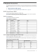
Table B-1 lists the DB-25 pin assignments on the 8 male connectors at the end of the AD278A
fan-out cable, or the 16 male ports on the AD281A port module.
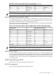
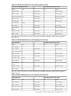
DB-25 Pin Assignments
Table B-1 lists the DB-25 pin assigments.
Table B-1 DB-25 Pin Assignments
Pin #DTE UseDescriptionSignal
ShellN/AChassis GroundGND
2OutputTransmitted DataTXD
3InputReceived DataRXD
4OutputRequest to SendRTS
5InputClear to SendCTS
6InputData Set ReadyDSR
7ReferenceSignal GroundSG
8InputData Carrier DetectDCD
20OutputData Terminal ReadyDTR
22InputRing IndicatorRI
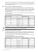
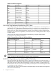
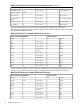
DB-25 Software Handshaking (XON/XOFF) Cable
The three-wire cable is sufficient for a terminal, printer, or other DTE (Data Terminal Equipment)
devices configured for software flow control.
Table B-2 lists the pin-out connection between the DB25 adapter and the DB-25 terminal/printer.
Table B-2 Simple Terminal/Printer Cable
DB-25 Male (Peripheral)DB-25 Female (Card End)
SignalPinPinSignal
RxD3Connected to2TxD
TxD2Connected to3RxD
SG7Connected to7SG
GNDShellConnected (via
shield) to
ShellGND
RS-232 Asynchronous: DB-25 33