
HP AD278A and AD279A PCI Multiplexer Support Guide, November 2008
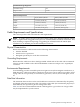
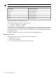
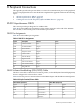
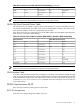
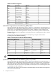
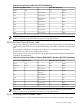
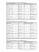
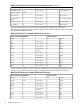

Table B-10 lists the pin-out connection between the RJ-45 adapter and the DB-25 modem cable,
and also shows how to apply the adapter wiring scheme to custom modem cables.
Table B-10 RJ-45 to DB-25 Modem Cable ( 10 Wire )
DB-25 Male (Modem End)RJ-45 10-Pin Plug (MUX Port End)
SignalPinPinSignal
RI22Connected to1RI
DSR6Connected to2DSR
RTS4Connected to3RTS
GND1 (or shell)Connected (via
shield) to
4GND
TxD2Connected to5TxD
RxD3Connected to6RxD
SG7Connected to7SG
CTS5Connected to8CTS
DTR20Connected to9DTR
DCD8Connected to10DCD
Cabling Pin-outs for HP Proprietory RJ45 and DB25 Devices
This section provides the pin-out connections between the AD278A/AD279A PCI Mux adapters
to HP proprietory RJ45 and DB25 devices.
NOTE: All RS-232 ports provide a standard RS-232 interface with full modem control signals
and surge protection on every signal.
Table B-11 shows the pin-out connection between the RJ-45 adapter and HP proprietary RJ-45
device.
Table B-11 RS-232 RJ-45 Pinouts to HP Proprietary RJ-45 Pinouts
RJ-45 (HP proprietory device end)RJ-45 10-Pin Plug (MUX Port End)
SignalPinPinSignal
2Data Set Ready
Clear to Send4Connected to8Clear to Send
10Data Carrier Detect
Signal Ground6Connected to7Signal Ground
Transmit Data3Connected to5Transmit Data
ShellChassis Ground
Receive Data1Connected to6Receive Data
9Data Terminal
Ready
Request to Send5Connected to3Request to Send
1Ring Indicator
Table B-12 shows the pin-out connection between the RJ-45 adapter and the HP proprietary
DB-25 device.
38 Peripheral Connections