HP X.
© Copyright 2007, 2011 Hewlett-Packard Development Company, L.P. Legal Notices Confidential computer software. Valid license required from Hewlett-Packard for possession, use or copying. Consistent with FAR 12.211 and 12.212, Commercial Computer Software, Computer Software Documentation, and Technical Data for Commercial Items are licensed to the U.S. Government under vendor’s standard commercial license. The information contained herein is subject to change without notice.
Contents 1 About the X.25 product...............................................................................7 Introduction..............................................................................................................................7 Application (L7), Presentation (L6), and Session (L5) levels.............................................................8 Transport level (L4)...................................................................................................................
X.25 Package definition.................................................................................................59 X.25 High availability configuration................................................................................60 Checking the configuration.............................................................................................60 Configuring the high availability feature for X.25 over LLC2.........................................................
Overview........................................................................................................................103 Configuring UUCP PAD support.........................................................................................103 Configuring the x29hosts file........................................................................................104 pad_uucp parameters..................................................................................................
Recovering from a power failure.............................................................................................135 For systems with a backup power supply.............................................................................135 For systems with no backup power supply...........................................................................135 Reporting problems...............................................................................................................
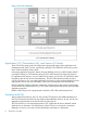
1 About the X.25 product Introduction The Hewlett-Packard X.25 link for HP 9000 systems provides networking link hardware and software to allow HP computer systems to communicate with other HP and non-HP computers over X.25 packet switching networks. The X.25 link implements the CCITT X.25 Recommendations and contains the components necessary to connect an HP 9000 to a public or private packet switching network conforming to the CCITT X.
Figure 1 X.25 Link architecture Application (L7), Presentation (L6), and Session (L5) levels The X.25 link does not provide any component for the general support of the application and presentation levels (levels 7 and 6, respectively), although X.25/9000 PAD Services do provide some of the functionality of these levels.
The X.25 link provides a BSD to PLP (Packet Level Protocol) translator to allow access to PLP at level 3 for user-written application programs via BSD IPC. The X.25 link also provides an OTS to PLP translator to allow access to PLP at level 3 for OSI Services via Xport OSI. Packet/Network level (L3) At the packet/network level (L3), X.25 link provides direct X.25 programmatic access via BSD IPC. For full details on X.25 programmatic access, refer to the X.
2 Installation Before you install the software Before installing the X.25 link software, check the requirements below to make sure that all required software and hardware has been correctly installed and configured. NOTE: This product is only supported on the system that is acting as a server. It is not supported on client systems. Hardware requirements This section describes the hardware requirements of the J2793B X.25 software for HP 9000 server systems. If you have not already done so, install the X.
Related Parameters • Level 3 window size (W in formulas below) as configured in the x25config file. • Level 3 packet size (P in formulas below) as configured in X.25 configuration file. • Socket buffer size (B in formulas below) used in your applications (setsockopt() system call). The default is 4 Kb. Evaluation Formulas The following formulas can be used to evaluate X.25 memory requirements: Memory for each VC (MVC) in bytes: MVC = (B x 3) + (2 x (W + 1) x P) Total Memory (TM) for X.
TM = (4096 x 3) + (2 x 3 x 1024)) x 200 + ((4096 x 3) + (2 x 5 x 128)) x 400 + (2 x 5120) TM = 9,123,840 (8.7 Mb) Software requirements Before installing the X.25 link product, make sure that the software listed below has been correctly installed on your system. Refer to the related publication if you need more information about any of these products. If you cannot find the software or information you need, contact your HP representative.
3 Configuration Configuring the X.25 link This section describes how to configure your X.25 link using HP System Management Homepage(SMH). HP SMH provides Graphical User Interface (GUI), Terminal User Interface (TUI), and Command Line Interface (CLI) for managing HP-UX. You can access these interfaces using the smh command (/usr/sbin/smh). If the DISPLAY environment variable is set, HP SMH opens in the default web browser. If the DISPLAY environment variable is not set, HP SMH opens in the TUI.
NOTE: Refer to “Using Non-English subscription forms” (page 141) for the English equivalents of the French, Italian, German, and Spanish fields that appear on non-English subscription forms. Using SMH’s on-line help The SMH on-line Help provides information (descriptions, formatting, and ranges) for all fields. You can access the SMH on-line Help system by: • Clicking on the Help button in a dialog or message box to display information about how to use the dialog, or about the message.
Table 1 Field descriptions (continued) Field Description to 4). Note that p and x are only required for systems with dual-port or quad-port cards. X.25 Address Address assigned to each local X.25 interface (card or port) by the network carrier. X.25 checks it for diagnostic and identification purposes only. This address is sometimes referred to as the X.121 address. Use the value given on your subscription form. Programmatic Access Name Name given to the interface you are configuring (used for X.
Figure 3 Configure X.25 virtual circuits (VCs) 2. Enter or modify field values as required (refer to the field descriptions below). When you configure the Quantity column (starting with the number of Permanent VCs), SMH automatically fills in the starting Logical Circuit Identification (LCI) as you Tab between fields. Table 2 Field descriptions 3. Field Description Permanent - Quantity Number of Permanent VCs. Use the value given on your subscription form.
Figure 4 Configure Internet address The Configure Internet Address dialog gives you a yes or no option to configure an IP address for this port. 2. Choose Yes or No to configure an IP address. If you select No, you indicate that no IP address is associated with this X.25 port. When you select No, all other fields in this dialog disappears. If you select Yes, you must fill in the other required fields in this dialog. 3. Enter or modify field values as required (refer to the following field descriptions).
Table 4 IP address and default subnet masks (continued) IP Address Class Default Subnet Mask A.B.C.* (A between 192 and 239) (B,C between 0 and 254) C 255.255.255.0 A.B.C.* (A between 240 and 254) D (B,C between 0 and 254) Not Allowed The Internet address is composed of two addresses: the network address and the subaddress. Zero (0) and -1 are not allowed in the subaddress. 4. If required, click Modify IP over X.25 Defaults to modify the Idle Timer, Hold Timer, MTU Size and System Max.
of service to which you subscribe. Refer to your Network Subscription Form for the correct values for your configuration. Follow the steps below to verify level 3 values: 1. At the Configure X.25 Card window, select Verify Level 3 Values. The following dialog appears: Figure 6 Verify level 3 values 2. Enter or modify field values as required (refer to the field descriptions below). Table 6 Verify level 3 values field descriptions 3.
Figure 7 Modify X.25 flow control defaults 4. Select either Modulo-8 or Modulo-128 to set level 3 Modulo parameters. The default is Modulo-8. The valid window-size values for Modulo-8 range from 1 to 7. For Modulo-128, the valid window-size values range from 1 to 127. NOTE: Flow Control Negotiation must be enabled on the “Verify Level 3 Values” dialog to allow the use of the negotiated flow control fields.
Table 8 Permanent VC flow control field descriptions 5. Field Description Packet Size: Inbound & Outbound Maximum packet size to be used over a PVC. The range is 16 through 4096 octets. The default is 128 for inbound and outbound packets. Use the value given on your subscription form. Window Size: Inbound & Outbound Maximum number of packets that can be transmitted without acknowledgment over a PVC. The range is 1 through 7 for Modulo-8, and 1 through 127 for Modulo-128.
Table 10 Throughput classes and line speeds (continued) 7. CCITT class number Line speed Baud rate (bps) 7 1200 8 2400 9 4800 10 9600 11 19200 12 48000 13 64000 Click OK to return to the Configure X.25 Card window when you have finished verifying level 3 values. Verifying level 2 values Follow the steps below to verify level 2 values: NOTE: If you subscribe to a public network, the network provider will provide the appropriate settings for all level 2 parameters.
Table 11 Verify level 2 values field descriptions Field Description k - Level 2 Window Size Maximum number of frames that can be transmitted without an acknowledgment. The range is 1 through 7 for Modulo-8 and 1 through 127 for Modulo-128. The default is 7. Use the value given on your subscription form. T1 - Retransmission Timer Maximum number of milliseconds to wait for an acknowledgment before retransmitting a frame. The range is 100 to 12000. The default is 3000.
NOTE: System Administration Manager (SAM) is deprecated in the 11iv3 release of HP-UX. HP System Management Homepage (HP SMH), an enhanced version of SAM, is introduced for managing HP-UX. 1. 2. 3. If you have not already done so, type smh at the HP-UX prompt. At the SMH main window, select Tools. Numerous object lists are displayed. At the Networking and Communications window, highlight Hosts and click OPEN. Highlight Local Hosts and click OPEN.
6. If the Provide X.25 Information button is displayed, you must use it to configure X.25 information about the remote system. When you click on Provide X.25 Information, the following dialog appears: Figure 11 Provide X.25 information 7. Enter or modify field values as required (refer to the field descriptions below).
Table 13 Provide X.25 information field descriptions (continued) 8. Field Description Accept reverse charging Enable this field if you want the local system to accept collect calls from the remote system. If this field is disabled, no collect calls will be accepted. Closed user group Enable this field if you subscribed to a closed user group (CUG) and you want to use the CUG with this connection.
Table 14 Additional XOL specific configuration parameters (continued) Field Format Value XOL_destination_macaddr (replaces the MAC address in the lan_box_addr) One hexadecimal value. This value must be prefixed with 0x. The destination MAC address to which the XOL interface is connected. XOL_DSAP One hexadecimal value. This value must be prefixed with 0x. The destination SAP value of the peer XOL interface. Set the value of DSAP to any even value in the range 0x70 0x7e, both inclusive.
Example 1 Sample file with the old parameters in the old format device lan_box_id lan_box_addr lan00x7c 1 0x080009c4728a 0x7e Example 2 Sample file with the new parameters in the new format device XOL_logical_port_id XOL_destination_macaddr XOL_DSAP 0x72 XOL_SSAP 0x7C standby_device lan1 XOL_floating_macaddr lan0 1 0x080009c4728a 0x0060B0A4EBE5 A sample generic configuration file is available for reference. It is available in the /etc/x25 directory and the filename is x25init_llc2_smpl.
Example 3 LLC2 configuration # # Likely runstring: x25init -c x25init_llc2_smpl X.121 7111 # X.121 address X.121_packet '' “ (TransPacaddressing) # use a null (i.e.
def_outthruputclass 19200 # default thruput class flowcontrol on # flow control negotiation allowed neg_inpacketsize 128 # offered packet size if using flow control negotiation neg_outpacketsize 128 # offered packetsize if using flow control negotiation neg_inwindow 7 # offered window size if using flow control negotiation neg_outwindow 7 # offered window size if using flow control negotiation thruputclass on neg_inthruputclass 19200 # offered thruput class if using thruput class negotiation neg
1. Run the following command at the CISCO console: Configure Terminal 2. Run the following command at the CISCO console: x25 route ^ 7111 interface FastEthernet1/10 mac 0011.0a80.31d6 3. Run the following command at the CISCO console: x25 route ^ 7222 interface FastEthernet1/10 mac 0800.09c4.728a 4.
Figure 12 One Lan, two boxes configuration To connect HOST to BOX 0 To implement the above configuration, the following configuration files need to be created on the HOST system. • Generic X.25 configuration file, x25_host_box_0 • LLC2 configuration file, llc2_lan_0 The generic X25 configuration file has to be created in the /etc/x25 directory using the example configuration file, /etc/x25/x25init_def. The file x25_host_box_0 should contain all the mandatory level 2 and level 3 parameters.
Stopping: To stop the configuration execute the following commands: x25stop -d lan0 -L 0 # stop XOL interface with logical port id 0 on lan0 x25stop -d lan0 -L 1 # stop XOL interface with logical port id 1 on lan0 To Connect Box 0 to HOST To implement the above configuration, the following configuration files need to be created on the BOX 0. • Generic X.
XOL_SSAP 0x7E The LLC2 specific configuration file, llc2_lan_2 is created in the /etc/x25 directory with the following entries: lan2 1 To start and stop above configuration: Starting: Execute the following commands at the command prompt: x25init -c x25_box_1_host -L llc2_lan_2 Stopping: To stop the configuration, execute the following commands: x25stop -d lan2 -L 0 # stop XOL interface with logical port id 0 on lan2 Configuring two Lans, with one box per Lan A graphical representation of the above configur
To configure Host to LAN 1 to BOX 1 To configure the Host to LAN 1 to BOX 1 communication, the following configuration file need to be created. • X.25 generic configuration file, x25_lan_1_box_1 • LLC2 configuration file, llc2_2_lan_0_lan_1 The x25_lan_1_box_1 file is created in the /etc/x25 directory. It will contain all the level 2 and level 3 parameters.
x25init -c x25_box_0_host -L llc2_lan_2 Stopping: To stop the configuration, execute the following commands: x25stop -d lan2 -L 0 # stop XOL interface with logical port id 0 on lan2 To Connect Box 1 to HOST To implement the above configuration, the following configuration files need to be created on the BOX 1. • Generic X.25 configuration file, x25_box_1_host.
Action: • Check the remote node’s hardware address using lanscan. Use the same hardware address in the generic X.25 configuration file. If you modify the hardware address to correct the error then, re-initialize the card using x25init. • If the nodes are connected back to back, check if the SAPs are identical for both the nodes in the generic X.25 configuration file.
Table 15 Additional XOT specific configuration parameters (continued) Field Format Value neg_outwindow A valid Window size. Outgoing Window Size for SVC. pvc_inpacketsize A valid packet size between 128 and Incoming packetsize for PVC. 4096 octets. Recommended X.25 packet size for XOT is 1024 octets. pvc_outpacketsize A valid packet size between 128 and Outgoing packetsize for PVC. 4096 octets. Recommended X.25 packet size for XOT is 1024 octets. pvc_inwindow A valid Window size.
Example 4 Sample X.25 configuration file # # Likely runstring: x25init -c /etc/x25/x25init_xot_def -X /etc/x25/x121_to_ip_map X.121 55555 # X.121 address X.121_packet 55555 # use a null (i.e. length 0) packet # address (TransPac addressing) name xot0 # interface name for Level 3 access # It MUST be of the format xot # where "instance number" can take a value from 0 to 9 # # XOT Specific Parameters # local_tcpip_address 10.0.0.
neg_outthruputclass 19200 # offered thruput class if using thruput class negotiation # # Parameters for PVCs # pvc_inpacketsize 1024 # packetsize for PVCs pvc_outpacketsize 1024 # packetsize for PVCs pvc_inwindow 7 # window size for PVCs pvc_outwindow 7 # window size for PVCs XOT specific Configuration File This is an XOT specific configuration file and contains information about every participating X.25 system and their IP Addresses. It is unique to the host.
x25init -c config_file -X xot_config_file where: config_file is the generic X.25 configuration file. xot_config_file is the XOT specific configuration file. IMPORTANT: When executing the x25init command to initialize the XOT interface, it is mandatory to specify both the Generic X.25 configuration file and the XOT specific configuration file as arguments. They must be specified with the absolute paths.
X.121 Address: 11111 Machine B: IP Address: 10.0.0.3 XOT Interface: xot0 X.121 Address: 22222 Number of two-way SVCs on machines A and B: 255 Figure 14 Switched virtual connection (SVC) over XOT setup To implement this configuration, the following files need to be created on machines A and B: • Generic X.25 configuration file, x25init_xot_def • XOT specific configuration file, x121_to_ip_map Both files must be created in the /etc/x25 directory.
Example 6 Generic X.25 configuration file x25init_xot_def on machine A # # Likely runstring: x25init -c /etc/x25/x25init_xot_def –X /etc/x25/x121_to_ip_map X.121 11111 # X.121 address X.121_packet 11111 # use a null (i.e. length 0) packet # address (TransPac addressing) name xot0 # interface name for Level 3 access # It MUST be of the format xot # where "instance number" can take a value from 0 to 9 # # XOT Specific Parameters # local_tcpip_address 10.0.0.
# # Parameters for PVCs # pvc_inpacketsize 1024 # packetsize for PVCs pvc_outpacketsize 1024 # packetsize for PVCs pvc_inwindow 7 # window size for PVCs pvc_outwindow 7 # window size for PVCs 44 Configuration
Example 7 TCP configuration file x121_to_ip_map on machine A # # X.25 to IP Map File for SVCs, as per RFC 1613 # #Destination X.21 Destination # Address IP Address 11111 10.0.0.1 22222 10.0.0.3 Configuring X.
Example 8 Generic X.25 configuration file x25init_xot_def on machine B # # Likely runstring: x25init -c /etc/x25/x25init_xot_def –X /etc/x25/x121_to_ip_map X.121 22222 # X.121 address X.121_packet 22222 # use a null (i.e. length 0) packet # address (TransPac addressing) name xot0 # interface name for Level 3 access # It MUST be of the format xot # where "instance number" can take a value from 0 to 9 # # XOT Specific Parameters # local_tcpip_address 10.0.0.
# # Parameters for PVCs # pvc_inpacketsize 1024 # packetsize for PVCs pvc_outpacketsize 1024 # packetsize for PVCs pvc_inwindow 7 # window size for PVCs pvc_outwindow 7 # window size for PVCs Example 9 TCP configuration file x121_to_ip_map on machine B # # X.25 to IP Map File for SVCs, as per RFC 1613 # #Destination X.21 Destination # Address IP Address 11111 10.0.0.1 22222 10.0.0.
Figure 15 Permanent virtual connection (PVC) over XOT setup To implement this configuration, the following files need to be created on machines A and B: • Generic X.25 configuration file, x25init_xot_def • TCP configuration file, x121_to_ip_map Both files must be created in the /etc/x25 directory.
Example 10 Generic X.25 configuration file x25init_xot_def on machine A # # Likely runstring: x25init -c /etc/x25/x25init_xot_def –X /etc/x25/x121_to_ip_map X.121 11111 # X.121 address X.121_packet 11111 # use a null (i.e. length 0) packet # address (TransPac addressing) name xot0 # interface name for Level 3 access # It MUST be of the format xot # where "instance number" can take a value from 0 to 9 # # XOT Specific Parameters # local_tcpip_address 10.0.0.
neg_outthruputclass 19200 # offered thruput class if using thruput class negotiation # # Parameters for PVCs # pvc_inpacketsize 1024 # packetsize for PVCs pvc_outpacketsize 1024 # packetsize for PVCs pvc_inwindow 7 # window size for PVCs pvc_outwindow 7 # window size for PVCs 50 Configuration
Example 11 TCP configuration file x121_to_ip_map on machine A # # X.25 to IP Map File # SVC Routing Information, as per RFC 1613 # #Destination X.21 Destination # Address IP Address 11111 10.0.0.1 22222 10.0.0.3 # # PVC Routing Information, as per RFC 1613 # Local(LCN), Remote(LCN), LocalInterfacename, RemoteInterfacename,Remoteip pvcroute 1 3 xot0 xot0 10.0.0.3 #PVC channel 1 mapped to channel 3 pvcroute 2 2 xot0 xot0 10.0.0.3 #PVC channel 2 mapped to channel 2 pvcroute 3 1 xot0 xot0 10.0.0.
Example 12 Generic X.25 configuration file x25init_xot_def on machine B # # Likely runstring: x25init -c /etc/x25/x25init_xot_def –X /etc/x25/x121_to_ip_map X.121 22222 # X.121 address X.121_packet 22222 # use a null (i.e. length 0) packet # address (TransPac addressing) name xot0 # interface name for Level 3 access # It MUST be of the format xot # where "instance number" can take a value from 0 to 9 # # XOT Specific Parameters # local_tcpip_address 10.0.0.
neg_outthruputclass 19200 # offered thruput class if using thruput class negotiation # # Parameters for PVCs # pvc_inpacketsize 1024 # packetsize for PVCs pvc_outpacketsize 1024 # packetsize for PVCs pvc_inwindow 7 # window size for PVCs pvc_outwindow 7 # window size for PVCs Example 13 TCP configuration file x121_to_ip_map on machine B # # X.25 to IP Map File # SVC Routing Information, as per RFC 1613 # #Destination X.21 Destination # Address IP Address 11111 10.0.0.1 22222 10.0.0.
[x25init] nc open of module x25tun0 failed CAUSE : Command has returned a bad exiting value ACTION : Contact your system administrator [x25init] Starting the X.25 stack failed. CAUSE : Command has returned a bad exiting value ACTION : Contact your system administrator [x25init] Configuration initialization failed Cause: The x25tun kernel module is set to “unused” state.
If the pathnames of the arguments is not similar to the example, execute the command with the absolute pathname. 2. Cause: The local_tcpip_address field in the XOT configuration file has a duplicate IP address. Solution: Check the log file, /var/x25/log/XOT_.log for an entry similar to the following: # cat /var/x25/log/XOT0_110201.log 20:06:12.582: xotWork_StartListen: failed to bind to port 1998, error=227 20:06:12.
• PAD printer server • PAD UUCP server • X.3 sets of parameters See “PAD services” (page 94) for detailed reference information on PAD services. This section assumes that SMH is running and that you are starting from the main window. If this is not the case, type smh at the HP-UX prompt before continuing. Remember to use the Help button (in the SMH window) to display information and instructions for the content of each field.
Add/Modify PAD printers server Follow the steps below to add or modify remote PAD printers: 1. 2. 3. At the SMH main window, highlight Networking and Communications and select Open Item from the Actions menu. At the Networking and Communications window, highlight X.25 PAD Services and select Open Item from the Actions menu. Highlight Printers Server and select Open Item from the Actions menu. SMH lists all remote printers that your system can currently access via X.25. 4. 5. 6. 7. 8.
NOTE: The X.3 values that you configure here are initially downloaded to the PAD. As the terminal characteristics of your session change, the X.25 software automatically downloads new values for certain parameters. Do not be alarmed if the values of some parameters are different from the values you initially specified. 1. 2. 3. At the SMH main window, highlight Networking and Communications and select Open Item from the Actions menu. At the Networking and Communications window, highlight X.
X.25 Cluster definition To configure a High Availability cluster, use SMH to define all cluster systems by giving their: • NODE_NAME • NETWORK_INTERFACE • HEARTBEAT_IP X.25 Commands to be configured in high availability packages Start X.25 link x25init -c x25config -a ipmap -d x25dev (see x25init (1m)) Stop X.25 link x25stop -d x25dev (see x25stop (1m)) Monitor X.25 link x25ifstate -d x25dev -H (see x25ifstate (1m)) X.25 Package definition An X.25 package is needed for each HA X.25 node.
X.25 High availability configuration Figure 16 X.25 High availability configuration Example 14 One example of remote failure The only file that contains the X.25 commands to run for High Availability is the /etc./ cmcluster/pkg*/control.sh file (one per X.25 package). # SERVICE NAMES AND COMMANDS SERVICE_NAME [0] =pkg1.
X25CHECK (c) COPYRIGHT Hewlett-Packard Company 1988. Test Starts on .. Wed Dec 8 09:15:01 1993 Initialization of the test... CALL packet sent ... The following figures have been measured on the network: Set up time : 267 ms Remote Connection Succeeded Execute the x25check command again, but this time with data packets: $ x25check 250207 -s 32 -n 1 X25CHECK (c) COPYRIGHT Hewlett-Packard Company 1988. Test Starts on .. Wed Dec 8 09:15:47 1993 Initialization of the test... CALL packet sent ...
transparent from the XOL router side or peer system, which sees the same MAC address associated with the active interface. NOTE: To avoid MAC address collision, the system administrator must identify an unused, unique MAC address in their LAN subnet. The lanadmin command is used to change the MAC address of the card. After failover, the failed LAN card is reconfigured with its factory default MAC address. XOL is not supported over APA (Auto Port Aggregation).
Figure 17 Before the failover When the lan0 (the primary LAN card) fails, the XOL interface stops on lan0, and a XOL interface is brought up automatically on lan1 (the standby LAN card on system A) using the same configuration file. An attempt is made to configure lan0 with the factory default MAC address, and uMAC is assigned to lan1 on system A during the local failover. The X.25 connection must be re-established on the XOL interface.
NOTE: The XOL HA feature is enabled by default in HP-UX 11i v3. Therefore, the -enableXOLHA option is no longer required. 1. To configure the standby device and the unique MAC address in the configuration file of the XOL primary interface, modify the following syntax: Standby_device standby LAN card name # used for local failover XOL_floating_macaddrunique MAC address NOTE: Local failover is automatically enabled by defining a standby_device in the configuration file.
MAC address is uMAC for that LAN segment. It is initially assigned to the card lan0 on primary system A. Figure 19 Before the failover If the SG package for XOL detects an error in the XOL interface, the package is stopped on the primary system and the equivalent package starts on the standby system. When the SG package is stopped on system A, the XOL interfaces (and optionally applications) on the failed LAN card are stopped.
XOL cluster definition You must define the cluster by providing the system names that are part of SG cluster. X.
Example 16 XOL SG package for remote failover # SERVICE NAMES AND COMMANDS SERVICE_NAME [0] =pkg1.Service_Name_01 (same SERVICE_NAME as in pkg conf) SERVICE_CMD [0] ="/usr/sbin/x25ifstate -d /dev/x25_0l1 -H " SERVICE_RESTART [0] = " " # Unique MAC address in the subnet (LAN segment), which is # not in use. This will be the Active MAC address on the # active node in the cluster.
NOTE: Enabling or disabling of HA feature for XOL interface is system wide. Before enabling or disabling the HA feature on a system, all existing XOL interfaces must be stopped. The XOL HA feature is enabled by default on 11i v3. 1.
Example 18 Remote failover with local failover support The following two entries must be added to the LLC2 configuration file: standby_device lan2 # lan2 is standby LAN. XOL_floating_macaddr 0x0060B0A4EBE5 # Unique MAC address in the subnet The SG package file that contains the X.25 commands is /etc./cmcluster/pkg*/ control.sh file (one per XOL package). # SERVICE NAMES AND COMMANDS SERVICE_NAME [0] =pkg1.
# START of customer defined halt commands. /usr/sbin/x25stop -d /dev/x25_1l0 Sleep 2 # Assuming that lan2 was configured as standby lan /usr/sbin/x25stop -d /dev/x25_2l0 Sleep 2 test_return 52 # END of customer defined halt commands } Verifying the X.25 link After completing the installation and configuration instructions, follow these steps to verify your link: 1. If you are using IP over X.25, use the ping command to check that the IP connection is operating properly.
4 OLA/R overview and concepts Introduction The letters O, L, A and R stand for On Line Addition [and] Replacement. This, of course, refers to the ability of a PCI I/O card to be replaced/added to an HP-UX computer system designed to support this feature without the need for completely shutting down, then re-booting the system or affecting other system components. The system hardware uses the per-slot power control combined with operating system support to enable this feature.
Card compatibility On-line addition When on-line adding an interface card, the first issue that must be resolved is whether the new card is compatible with the system. Each OLA/R-capable PCI slot provides a set amount of power. The replacement card cannot draw more power than is available. The card must also operate at the slot’s bus frequency. A PCI card must run at any frequency lower than its maximum capability, but a card that could only operate at 33 MHz would not work on a bus running at 66 MHz.
Fortunately SMH performs a thorough critical resource analysis automatically, and presents options to you based on its findings. If you determine that critical resources will be affected by the procedure, you could replace the card when the server is off-line, or if you must take action immediately, you can use rad to attempt an on-line addition of a backup card and deletion of the target card.
Table 17 Three possible critical resource analysis (CRA) outcomes (continued) Outcome Notes Screen Displays Buttons Activated Analysis complete” messages. User Actions change to the system. Or, Remove all cables from the PCI I/O card and click OK to take you to the next step. Critical resource(s ) identified. SMH will not allow the operation to proceed. Detailed message describing the affected critical resource. Other resources identified.
15. SMH completes the operation by reversing the sequence of actions. That is, SMH will: • return power to the card slot, and enables power to the Green LED • identify the new card • resume driver operations to the card 16. Connect the cables to the card. How to on-line add (OLA) a J3525A PCI card using SMH NOTE: On-line addition will recognize and claim the interface card only if the X.25/9000 software is already loaded on the system.
Table 18 Three possible critical resource analysis (CRA) outcomes (continued) Outcome Notes Screen Displays Buttons Activated User Actions your knowledge of the current system configuration. SMH displays a dialog indicating that the selected slot has power disabled and it is now safe to add the card to the desired slot. 9. At this point, the amber LED is activated and the green LED is off. Now add the new PCI card. Refer to the system manual for the insertion of the PCI card.
5 Diagnostic utilities Using diagnostic utilities This chapter describes how to use the X.25 diagnostic utilities. The diagnostic utilities provided with your X.25 link are described briefly in the following table. Refer to “Troubleshooting” (page 130) if you need help deciding which utility to use. Table 19 Available diagnostic utilities Utility Description Refer to: x25checkx25server Tests connectivity up to X.25 level 3 man page and this chapter for between the local and remote nodes.
Figure 21 Scope of X.25 diagnostic utilities Before using the diagnostic utilities Some of the diagnostic utilities request or display information about the X.25 interface card using one or more of the naming conventions described below. Keep these conventions in mind when using the diagnostic utilities: • the name of the device file, uses the format x25_npx, where n represents the card instance number (0 to 15).
background process that waits for call requests from x25check. The x25server must be running before you execute x25check. See the man pages for x25check and x25server for syntax and parameter information.
NOTE: 80 Diagnostic utilities The x25server daemon will be killed if all of the X.25 interfaces are deactivated.
Example 19 Running x25check interactively (no parameters) The example below shows x25check used interactively to do three tests. • The first test (sending a call packet only) is successful and the results are shown. (Generally, when running x25check, first send the CALL packet alone, without data, to verify that a VC has been established between the nodes). • The second test uses the same destination address to send five data packets. Note that the X.
Unable to Connect to Remote NodeVC_CLEAR Packet was received with CAUSE 0 : DTE Originated DIAG 245 : Cannot Interpret Diagnostic Code Example 20 Running x25check with an X.121 address In the example below, the destination X.121 address of the destination node is specified as a parameter to x25check. This example shows a successful test and assumes the closed_user_group to be 51. $ x25check 250207 -i interface0 -g 51 X25CHECK (c) COPYRIGHT Hewlett-Packard Company 1988. Test Starts on ..
Example 22 Displaying the current configuration x25stat -c -d x25_0 -------- X.25 CONFIG ----------General Parameters: X.121 Address: 110 X.121 Pkt Addr: 110 Programatic Access Name: x25interface_0 Level 1 parameters Linespeed: external clock Level 2 parameters t1 [frame timeout]: 3000 ms t3 [idle timer]: 12000 ms n2 [retransmissions]: 3 Max.
Example 23 Displaying Global statistics for XOT See the table provided after this example under the heading “SUBNETWORK STATISTICS FOR X25” for help in interpreting the displayed “State” of the X.25 link.
Registration Reg confirm Packets(total) Bytes(total) 0 0 5 640 0 0 5 640 The level 3 “State” under the heading “SUBNETWORK STATISTICS FOR X25” can be: Table 20 Level 3 state Output on Screen Description/Meaning Link not up X.
Example 24 Displaying global statistics for X.25/LAPB See the tables provided after this example under the headings “SUBNETWORK STATISTICS FOR X25” and “STATISTICS FOR LAPB” for help in interpreting the displayed “State” of the X.25 link.
0 CRC/frame errors received 0 received frames with no buffer 0 received frames with no flow control 0 receive buffer overflows The level 3 “State” under the heading “SUBNETWORK STATISTICS FOR X25” can be: Table 21 Level 3 state Output on Screen Description/Meaning Link not up X.
The output under the heading “STATISTICS FOR WAN” is explained in the table below: Table 24 Statistics for WAN output 88 Output on Screen Description/Meaning transmit underruns Shows the number of times a transmission was aborted because the next octets to be transmitted were not provided soon enough for the level 2 firmware receive overruns Shows often-received octets were overwritten because they were not processed by the card received frames with no buffer No message available in level 1 to copy
Example 25 Displaying virtual circuit data packet counters The following example shows the output when there is one virtual circuit connected. Note that the virtual circuit specified in the command line is 64, in decimal. The LCN shown in the example output is displayed as 40, the hexadecimal equivalent of 64.
Example 26 Displaying global X.
Example 27 Displaying X.
Table 26 Statistics for WAN output (continued) Output on Screen Description/Meaning transmit underruns Shows the number of times a transmission was aborted because the next octets to be transmitted were not provided soon enough for the level 2 firmware receive overruns Shows often-received octets were overwritten because they were not processed by the card received frames with no buffer No message available in level 1 to copy received data to received frames with no flow control Never used receive
Table 27 Example statistics for x25mibstat (continued) Statistic x25mibstat Option Remark Clear information -s x25statEntry -s mioxPleEntry About clear initiator About refused calls -s lapbFlowEntry Number of LAPD-B state changes Clear information x25mibstat 93
6 PAD services Introduction This section describes X.25/9000 PAD (Packet Assembler/Disassembler) Services which enable HP 9000 computers to connect and communicate with remote systems over a Packet Switching Network (PSN). NOTE: Refer to “Configuring PAD services” (page 55) in Chapter 3 for information on configuring PAD Services with SMH.
PAD services and the HP 9000 host All of the PAD services can be seen as a pipe through which data is passed from X.25 to the PTY (Pseudo Type) terminal and vice versa (see the illustration below). Terminal data is not modified, but the X.25 headers are stripped before data reaches the PTY. Figure 23 PAD services as a pipe Remote PAD support (x29server) Overview The x29server user-level process provides support for communications with terminals attached to a remote PAD. This process accesses X.
Call acceptance mechanism and system security The x29server process operates in conjunction with devices declared in the set of pad_spt (PAD support) entries contained in the x29hosts file. It continually “listens” to the network and initializes communications channels at the user level when a call request is received. x29server can handle a large number of calls because each communication channel is managed by an independent process. The x29server process employs Berkeley Sockets (at X.
parameters for each remote device and the x3config file contains X.3 communications profile parameters for each device declared in the x29hosts file. See “X.25 Configuration files and examples” (page 144) for examples of the x29hosts and x3config files. Configuring pad_spt Parameters Remote PAD support parameters are specified in the pad_spt section of the x29hosts file. An example pad_spt section with parameter values is shown below.
If the pty_slave_fname field contains an entry, x29server considers any communication initiated by this entry to be restricted to exclusive use by the TTY/ PTY (master/slave) pair. The call is refused if the TTY/PTY pair does not exist, is already in use, or cannot be accessed (permission should be set to 666). logging Optional. Specifies the logging level for each call.
If the application and cud fields do not appear in the pad_spt file, the /bin/login (default) program is automatically launched. CAUTION: Use extreme caution when specifying applications other than the default (login) application. Since the x29server process is started with superuser privileges, it gives root privileges to applications triggered by incoming calls.
System requirements Because each printing device requires system resources, HP recommends that the kernel parameters be set to following values (or greater): • MAX_PAD_PR – is the number of PAD printers to be configured.
logging Optional (default = 1). This is the logging level used for each printer device. Printer device logging can be set to 0, 1, 2, or 3 where the respective values are: 0 – No logging (do not create a log file). 1 – Minimum session error logging. 2 – Error and warning logging. 3 – Error, warning, information, and status logging. HP recommends logging level 0 or 1 for normal operation. Logging levels 2 and 3 should only be used for troubleshooting for short periods of time.
which is profile 21 on HP 2335a. On the host side, the printer name is foo. This means that when a user types lp -d foo /tmp/file, the file /tmp/file will be printed on this printer. The X.25 interface on the host is interface0. Printer configuration To configure a printer (for in the examples below) for use with the standard UNIX LP spooler system and x29printd, follow these steps: 1.
UUCP support (x29uucpd) Overview x29uucpd provides UUCP connectivity on X.25 networks using CCITT Recommendations X.3 and X.29. With x29uucpd, users on HP 9000 host systems with X.25 access and UUCP can execute UUCP subsystem commands to other systems running X.25, PAD support, and UUCP. x29uucpd interfaces with the X.25 subsystem through BSD Sockets to initiate call request packets to remote systems on X.25. When a call request arrives at a destination system, it is received by the PAD support service.
NOTE: See the man pages for x29uucpd for full details on syntax and parameters. File Contents /etc/x25/x29hosts pad_uucp parameters for each remote host /etc/passwd uucp entry /etc/x25/x3config optional X.3 parameters /usr/lib/uucp/Systems remote system’s name /usr/lib/uucp/Permissions remote system’s login name /usr/lib/uucp/Devices device file name Configuring the x29hosts file The /etc/x25/x29hosts file must contain a separate pad_uucp section for each remote site.
2 – Error and warning logging. 3 – Error, warning, information, and status logging for troubleshooting. HP recommends using log level 0 (no logging) for normal operation. reverse_charge Optional (default is disable). Specifies the reverse charge option for call setup at this address. Possible settings are disabled (or disable) and enabled (or enable). When reverse charge is enabled, x29uucpd sends out call request packets with reverse charge requested. x3 Optional. This is the X.
MACHINE=bill \ SENDFILES=yes REQUEST=yes CALLBACK=no \ READ=/ WRITE=/ COMMANDS=ALL NOTE: 5. You can verify current permissions with the uucheck -v command. Create the following entry in the /etc/x25/x29hosts file: pad_uucp { device bill name interface0 remote_x121 [bill’s X.121_address] logging 3 x3 default_x3 } Refer to “Configuring the x29hosts file” (page 104) earlier in this section for the definitions of these parameters. 6. Launch /usr/sbin/x29uucpd at the HP-UX command prompt.
bill# x25server dave# x25check [bill’s X.121 address] If successful, you will receive the message “Remote connection succeeded.” 12. Test the files: x29hosts, x3config (at bill) using: dave# padem [bill’s X.121 address] If successful, you will receive the “login” message and you will be able to enter your details. 13.
got it sendthem (ˆMDELAY ˆMDELAY ˆMˆM) expect: (ogin:) /* reception of “bill”’s banner*/ ˆMGeneric-Sys (generic) [HP Release A.B9.04]ˆ Mˆ Mlogin:got it sendthem (uucpˆM) enter ub_sst, status is : 0 Rmtname: bill imsg > ˆMˆMˆJlogin: ˆMˆMˆJlogin: ˆMˆMˆMˆJlogin: ˆMˆJlogin: uucpˆMˆMˆJPlease wait ..
The padem program operates in either command or data transfer mode. The operating mode depends on whether an X.121 address or a symbolic address is specified when padem is launched. Command mode If the X.121 address or symbolic address of the remote host is not specified, padem begins execution in command mode and prompts the user for commands with X28> (the padem prompt). In command mode, padem receives X.28 PAD commands from users. Any padem command can be entered at the prompt.
If this entry exists, any call to the remote X.121 address will use the associated fields (logging, reverse_charge, profile, and name). name Optional. This is the name of the programmatic interface used for call setup. If this entry does not exist, the default name associated with /dev/x25_0 is used. This name must match the programmatic access name (also called name) in the X.25 configuration file. logging Optional. Specifies the logging level that applies to all calls made during this session.
Table 28 X.28 PAD command set (continued) PAD Command Set Description reset Resets a virtual circuit (VC). When a VC is reset, all data received (but unread) is lost, and all X.3 parameters are set to the default values (as they were defined before the VC was established). set n:v [,n:v] Sets the X.3 parameter n to value v. If there is a syntax error, padem responds with an ERR service signal and updates the diagnostic text.
Each of the 22 parameters has an identifier known as the parameter reference. This identifier is an integer value from 1 to 22. Each parameter has a defined range of possible values as specified by the X.3 recommendations. X.3 parameters are specified in one or more configuration sets contained in the /etc/x25/ x3config file. Each configuration set includes: • X.
Modifying parameters Initial parameter settings can be changed at any time during a call. This occurs when x29server detects an ioctl() call to configure the PTY for a PAD terminal. This system call could be issued by the UNIX login process, by a shell initialization script such as .login, or by an application. Each ioctl() request is examined by the server. If a mapping exists between the terminal I/O parameter and X.3, the terminal I/O value is checked against the current X.3 setting.
Value Meaning 4 ESC, BEL, ENQ, and ACK only. 8 DEL, CAN, and DC2 only. 16 ETX and EOT only. 32 HT, LT, VT, FF only. 64 NUL, SOH, STX, BS, LF, CR, SO, SI, DLE, DC1, DC3, DC4, NAK, SYN, ETB, EM, SUB, FS, GS, RS, and US (all other characters in the first two columns of the International Alphabet #5). 126 All characters, except alphanumerics. 127 All characters are data forwarding. NOTE: The values listed for parameter 3 may be combined by specifying the sum of the values.
X.3 Parameter Description 10 - Chars per Line/Wrap -Around Specifies the number of printing characters to be transmitted before the PAD inserts a carriage return in the data stream. This parameter is not needed on terminals with auto-wrap-around. The range is 0 through 255. 11 - Baud This parameter specifies the terminal access speed (Baud rate). x29server does not allow users to change the Baud rate. It defaults to the terminal Baud rate, which is usually 9600.
NOTE: The values listed for parameter 13 may be combined by specifying the sum of the values. For example, specifying 3 is the same as specifying 1 and 2. X.3 Parameter Description 14 - Line Feed Padding Specifies the number of padding characters to be added following a line feed. This is used for hard copy terminals to allow time for the paper to be moved up. The range is 0 through 7.
NOTE: The values above may be combined by specifying the sum of the values. For example, specifying 3 is the same as specifying 1 and 2. This parameter is available only for networks using the 1984 or 1988 standards. X.3 Parameter Description 21 - Parity Specifies how parity should be treated. The possible values are shown below. Value Meaning 0 No parity checking or generation. 1 Parity checking. 2 Parity generation. 3 Parity checking or generation.
7 Tracing and logging utilities Introduction This chapter describes the use of the X.25 tracing and logging utilities provided with your X.25 link. These utilities are briefly described in the following table. Refer to Chapter 8, “Troubleshooting” (page 130), if you need help deciding which utility to use. Table 31 Available tracing and logging utilities Utility Description Refer to: nettl Creates a user-defined log file containing frame and packet trace information from X.25 packet and LAP-B levels.
nettl Use this command to create an X.25 trace file. The description below is limited to the context of X.25 and assumes that nettl is already operating on your system. For XOT, Level 3 packets cannot be traced directly as it is done over XOL or the X.25 card. Instead, an alternate tracing mechanism has been introduced. Since an XOT packet gets transmitted over the TCP stack, it can be captured by enabling nettl over the TCP subsystem.
NOTE: The .TRCX suffix is automatically appended to the output file where X starts at 0 and changes to 1 when the file becomes full. Traces are always written to the .TRC0 file. -card(-c) This option is required with the traceon command to specify the X.25 subsystem interface (port) name. The X.25 device is specified with x25_npx which identifies the interface defined in your X.25 configuration file.
-t records Lets you specify how many records you want to format from the end of the file. This enables you to get the most recent information. The maximum number of records is 1000. By default, all records are formatted. -f file_name Use this option to specify the binary file containing the log or trace data. This is the name of the .TRC0 file that was specified when nettl was run the first time with the -traceon and -file options. By default, data is read from standard input.
Example 3: This example explains how to format the trace file in “terse” (short) mode with no filtering. To format the file /tmp/tracex25.TRC0 in “terse” mode, with no filtering: /etc/netfmt -1 -f /tmp/tracex25.TRC0 | more The output will resemble the following: Tx board: 0 at 10:16:19.689181 Data Packet lci 64 PR: 0 PS: 0 Example 4: This example explains how to display the contents of the encapsulated X.25 Level 3 packet in case of XOT.
Device ID : -1 Path ID : 0 Connection ID : 0 Location : 00123 ~~~~~~~~~~~~~~~~~~~~~~~~~~~~~~~~~~~~~~~~~~~~~~~~~~~~~~~~~~~~~~~~~~~~~~~~~~~~ -------------------------------- TCP Header ---------------------------------sport: 49356 --> dport: 1998 flags: PUSH ACK seq: 0xeda04af3 urp: 0x0 chksum: 0x2f data len: 27 ack: 0x3f6de013 win: 0x8000 optlen: 0 --------------------------------- XoT Header --------------------------------Version :00 Length of XoT Data :23 Tx L3 bd: 0 at Thu Jan 13 IST 2011 01:39:53.
Table 33 Filter file options (continued) System/subsystem level Type Value SX25L3 (subsystem level) lci decimal number between 0 and 4095 (this can be a list or range of values) packet call, callc, clear, clearc, data, rr, rnr, interrupt, reset, resetc, restart, restartc, diagnostic, registration, reject family (refer to Table 34 (page 124) below) connect, disconnect, data, fctl, network The following table lists the packet types displayed for each value combined with family.
strace The strace command collects logging event messages from X.25 level 3 and X.25 level 2 STREAMS modules and writes them to standard output. strace runs until terminated by the user. See the man pages for strace((1))for a more detailed description. Running strace with several sets of arguments can impair STREAMS performance. Also, some messages may be lost if too many are logged at one time. HP recommends that you run strace as a background process with output directed to a file.
NOTE: The sub code for dual-port cards will be the same for both ports. A simple way to think of dual-port sub codes is as the decimal equivalent of 7030 + n (expressed in hexadecimal), where n is the card instance number. For example, for the device file x25_1p2, the sub in hexadecimal would be 7030 + 1 = 7031 which, when converted to decimal gives you 28721. Some sample calculations of the sub code for dual-port cards are provided in the table below.
Table 37 Output format (continued) Column Head X.25 level 2 (mod=201) IP over X.25 (mod=208) a Column Head Column Head pri 5 Interrupt/Int Conf (INT In/Out, INTC) pri 6 Data (DATA In/Out) pri 1 Link Up/Down pri 2 Link reset events (LINK Rst) pri 3 Frame Reject, Reject (FRMR In/Out, REJ In/Out) pri 4 Busy conditions (LINK Bsy) pri 0 IP over X.25 fatal error (call your HP representative) pri 1 IP over X.25 error (check configuration or addresses) pri 2 IP over X.
Frame Type Parameters Displayed FRMR In No parameter displayed FRMR Out “Rsn 1” means the control field received was not defined or not implemented. “Rsn 3” means the control field received was invalid. “Rsn 4” means the information field received was too long. “Rsn 8” means the control field received contained an invalid variable. REJ In/Out (level 2) “N(XX)” is an internal variable of no importance or meaning. LINK Bsy (level 2) “Local” means that the RNR has been sent.
324195 324196 324203 324204 14:59:59 14:59:59 14:59:59 14:59:59 33688087 33688087 33688091 33688091 6 6 2 2 ... ... ... ... 200 200 200 200 49 49 49 49 DATA In:‘31’ lci 400 ns/nr 0000 DATA Out:‘31’ lci 400 ns/nr 0001 CLR In: ‘31’ lci 400 C/D 00f2 CLC Out: ‘31’ lci 400 The command: strace 201 48 all gives the following output: 324790 15:06:17 33725841 1 ... 201 48 LINK Up : ‘30’ The command: strace 201 49 all gives the following output: 324893 15:07:18 33731984 1 ...
8 Troubleshooting Troubleshooting your X.25 link This section describes troubleshooting procedures for checking your X.25 link up to X.25 level 3. It also provides information on troubleshooting IP over X.25, as well as procedures for diagnosing switching problems. To use these procedures you should be familiar with the following commands: Table 39 Troubleshooting commands Command Purpose Refer to... x25init Initializes X.25 interface and software. man pages and examples at the end of Superuser only.
Figure 28 Flowchart 1 Flowchart 2 – Procedures and notes Use these procedures to verify that your X.25 link is correctly initialized. Read the following notes before carrying out the initialization check procedures in Flowchart 2. Note 2-1 – x25stat Level 2 is down if x25stat -d [device] -f returns a level 2 link state other than “normal.” Note 2-2 – eisa_config Sometimes x25init does not recognize the dual-port EISA interface (J2815A) after a first-time installation.
Figure 29 Flowchart 2 – Initialization check Flowchart 3 – Procedures and notes Use these procedures to verify that your hardware is properly connected and operating correctly. Read the following notes before running the hardware check procedures in Flowchart 3.
Figure 30 Flowchart 3 – Hardware check Flowchart 4 – Procedures and notes This flowchart describes how to run a loopback test using x25check on the local node. This checks that your X.25 link to the network or X.25 switch is working correctly. Note 4-1 – X25check You do a loopback test using the x25server and x25check commands. The x25server process is only used to accept and echo back an X.25 packet coming from an x25check process.
Figure 31 Flowchart 4 – X.25 Configuration check Flowchart 5 – Procedures and notes Use these procedures to verify your IP addressing and remote host connection. Note 5-1 – Ping Use ping on your own IP over X.25 address, for example: ping 195.25.0.13 Do not use aliases (for example, as defined in/etc/hosts), since this may introduce other errors. Use the Break key or Ctrl-C to terminate ping if you have not set the number of packets with the -n option. Note 5-2 – Checking your IP over X.
If no IP communication is possible (ping to a local IP address fails) and netstat -a shows no entries despite the fact that x25init reported a successful IP mapping, the likely cause is: • the device=x25_card_device parameter has not been added to the /etc/x25/ ip_to_x121_map file. See the section, “IP-to-X.121 address mapping table” (page 138) in this chapter. You can also use the netstat command with the -r option to get information about IP addresses associated with a particular interface.
Reporting problems If you have a service contract with HP, ask your service representative to document the problem as a Service Request (SR). Include the following information where applicable: • A detailed description of the problem. Describe the events leading up to the problem and the symptoms of the problem. Include information on HP-UX commands, communication subsystem commands, job streams, result codes, and error messages (the exact wording).
In order for two cards (on the same host) to communicate, one card must be configured as the DTE and the other card as DCE. To set up a card as DCE, use the x25init command and enter DCE_80, DCE_84 or DCE_88 (according to the standard you are using) in the networktype parameter. You must also make sure that the two cards are using compatible level 2 parameters. Once both cards are initialized, you can run x25check and x25server to verify the connections.
Command Description x25trace Protocol level tracing facility. See your man pages. x25upload Dumps the interface card memory into a file. See your man pages. nettl Creates a user-defined log file containing frame and packet trace information from X.25 packet and LAP-B levels. See your man pages for x25trace and the examples in “Tracing and logging utilities” (page 118). netfmt Formats trace information contained in the user-defined log file that was generated with the nettl command.
NOTE: If the destination host is only reachable through a gateway, you must have a route to that host (a host or a net route). The IP address in the table must belong to the same IP subnet as a configured card in your system, and this card must be already started when you initialize IP routing with the command: /usr/sbin/x25init -a /etc/x25/ip_to_x121_map NOTE: In case, the IP-to-X.
prog_access _name Specifies the card's programmatic access name. NOTE: For Series 712 workstations this is always name=interface0. +URC Specifies that outbound calls to this IP address will Use Reverse Charging (URC). -URC (Default) Specifies that outbound calls to this IP address will not Use Reverse Charging (URC).) +ARC Specifies that inbound calls to this IP address will Accept Reverse Charging (ARC).
A Using Non-English subscription forms Subscription form translations This appendix lists the English (SMH dialog field) equivalents for terms that appear on your French, Italian, German or Spanish subscription form. Use this information to locate the English SMH dialog field equivalents of these terms. Terms are listed in order of appearance. Online help (using the Help button) is available for each field. Table 40 French TRANSPAC subscription form English on SMH dialogs French on subscription form X.
Table 41 Using your ITAPAC (Italian) subscription form (continued) English on SMH dialogs Italian on subscription form Default Packet Size - Inbound & Outbound, Switched VC Flow Control Dimensione di default del pacchetto - uscente, controllo di flusso VC commutato Default Window Size - Inbound & Outbound, Switched VC Flow Control Dimensione di default della finestra - uscente, controllo di flusso VC commutato Packet Size - Permanent VC Flow Control Dimensione del pacchetto - controllo di flusso VC p
Table 43 Using your IBERPAC (Spanish) subscription form (continued) English on SMH dialogs Spanish on subscription form Packet Size - Permanent VC Flow Control Tamaño de Paquete - control de flujo en CV permanentes Switched VC Default - Inbound & Outbound (Modify Throughput Class Setting) CV conmutados por defecto - entrantes y salientes (Negociación de la Clase de Caudal) Switched VC Negotiated (Modify Throughput Class Setting) Clase negociada en CV conmutado (Negociación de la Clase de Caudal) k - L
B X.25 Configuration files and examples X.25 Configuration files This section lists X.25 configuration and addressing files. Table 44 /etc/x25 directory Configuration File Description x25config_0 ASCII file containing X.25 parameters. This file can be used by the x25init command when initializing the card. It is created automatically if you configure X.25 using SMH. To configure X.25 manually, copy and edit either x25init_def or x25init_smpl. x25init_def Contains default X.
Table 48 Home directory Configuration File Description .rhosts (optional) Security file which authorizes remote hosts and users on local host. See the man page for hosts.equiv. .netrc (optional) Contains login and initialization information used by the ftp auto-login process. See the man page for netrc. Example files This section provides example file listings for of the x25init_def, x_25init_smpl, x3config, x29hosts, and x25_networks files.
# disallow incoming calls requesting reverse changes def_inpacketsize 128 def_outpacketsize 128 def_inwindow 2 def_outwindow 2 # def_inthruputclass 19200 # def_outthruputclass 19200 # # # # # # default default default default default default packetsize packetsize window size window size thruput class thruput class flowcontrol off neg_inpacketsize 128 neg_outpacketsize 128 neg_inwindow 2 neg_outwindow 2 # flow control negotiation not allowed # offered pkt size if using flow control negotiation # offered
lci 1 pvc 5 lci 255 insvc 5 lci 2048 svc 6 # 5 permanent VCs # 5 one-way incoming SVCs # 6 two-way switched VCs networktype TRANSPAC fast_select enabled reverse_charge enabled # CCITT 1984, DTE (see /etc/x25/x25_networks) # allow incoming calls with call user data # allow incoming calls requesting reverse changes def_inpacketsize 128 def_outpacketsize 128 def_inwindow 7 def_outwindow 7 def_inthruputclass 19200 def_outthruputclass 19200 # # # # # # flowcontrol on neg_inpacketsize 128 neg_outpacketsize
16 17 18 19 20 21 22 8 24 0 1 0 0 0 } hp_uucp { 1 0 2 0 3 0 4 10 5 1 6 0 7 0 8 0 9 0 10 0 11 14 12 1 13 0 14 0 15 0 16 8 17 24 18 0 19 1 20 0 21 0 22 0 } hp_padsrvr { 1 1 1 2 1 1 3 94 127 4 0 0 5 1 1 6 5 5 7 21 21 8 0 0 9 0 0 10 0 0 11 14 14 12 1 1 13 0 0 14 0 0 15 1 0 16 8 8 17 24 24 18 0 0 19 1 1 20 0 0 21 0 0 22 0 0 } hp_profile : 0 { 1 1 2 1 3 127 4 0 5 1 6 5 7 21 8 0 148 X.
9 10 11 12 13 14 15 16 17 18 19 20 21 22 0 0 14 1 0 0 1 8 24 0 1 0 0 0 } The x29hosts file # for x29printd printer { device name remote_x121 x3 reverse_charge logging printer1 hptndxk0 408555111201 hp_printer enable 1 } # for x29uucpd pad_uucp { device name remote_x121 x3 reverse_charge logging x25uucp hptndxk0 4085551113 hp_uucp enable 3 } # for padem pad_em { name remote_x121 reverse_charge profile logging hptndxk0 4085551111 enable 0 3 } host_table { Gale Tornado Typhoon 4085551111 4085551113 4
The network type file (x25_networks) The network type file describes standard network types. If the network to which you are subscribing does not meet any of the network descriptions specified in this file, use one of the generic entries (DTE_80, DTE_84 or DTE_88). The network type file is read-only. The value in the first column of the file is an alias assigned to the network type. This is the value that you specify for the networktype configuration parameter in the x25init configuration file.
C Diagnostic messages Introduction This appendix describes the diagnostic codes and messages which are a subset of the list defined by the International Standards Organization (ISO) in IS-8202:1987(E). Only those diagnostics supported on X.25 for HP 9000 systems are listed. Each message is listed in numerical order by its diagnostic code and includes an ISO description and explanation. Refer to Appendix D of the X.
Packet codes RESTART packet codes When the system receives a RESTART INDICATION packet, the received CLEAR INDICATION or RESET INDICATION packet contains a cause code of 0 and the diagnostic code used in the RESTART. RESET/CLEAR packet codes The system may generate a RESET/CLEAR because of an error, lack of memory, or other condition. When this occurs, a RESET/CLEAR INDICATION is delivered to the application and a RESET/CLEAR REQUEST packet is sent to the network.
Table 51 Packet not allowed Diagnostic ISO Description Explanation 33 (RESTART, CLEAR, RESET) Unidentifiable packet. Packet that cannot be identified (3rd byte of the level 2 information field not defined in CCITT X.25 Recommendation received). REJECT or REGISTRATION packet received. 34 (CLEAR) Call on one way logical If configured as DTE, CALL INDICATION received with logical channel channel. identifier (LCI) corresponding to one-way logical channel outgoing.
Table 52 Timer expired (continued) Diagnostic 52 (RESTART) ISO Description Explanation retransmission count surpassed for RESET REQUEST). Count of RESET retries has been surpassed. CLEAR REQUEST has been sent. Timer expired for RESTART INDICATION (or DTE timer expired or retransmission count surpassed for RESTART REQUEST). RESTART CONFIRM not received within T20 time limit (set at approximately 180 seconds) after transmission of RESTART REQUEST.
Table 53 Call setup, call clearing, or registration problem (continued) Diagnostic ISO Description Explanation No combination of facilities can equal the value indicated in the packet’s facility length field. If this condition is detected in the CALL REQUEST packet it produces an error instead of a CLEAR. System could not add negotiation facilities without the facility field becoming larger than allowed by the configured revision level of the CCITT X.25 Recommendation (63 for 1980, 109 for 1984).
Table 56 DTE-Specific signals (continued) Diagnostic ISO Description Explanation X.121 address. Internal problem which may be generated by components of X.25/9000 architecture. 161 (RESTART) DTE operational. Level 2 is coming up or a SABM frame is received. System sends RESTART REQUEST indicating host is up. 162 (CLEAR, RESET) DTE not operational. Either level 3 or level 2 detected as down. Request delivered when network interface was not operational.
Table 57 OSI Network service problem (continued) Diagnostic ISO Description Explanation 235 (CLEAR) NSAP address unknown. CALL INDICATION was received with unknown NSAP address (first byte of call user data). 251 (RESET) Reset. Cause unspecified. System failed to synchronize data transfer to interface. Table 58 Higher level initiated Diagnostic ISO Description Explanation 241 (CLEAR) Disconnection normal.
Index Symbols .netrc file, 145 .rhosts file, 145 A accept reverse charge IP to X.121 mapping file, 140 add PAD-UUCP services, 57 add remote PAD support, 56 addresses summary of files, 144 The IP-to-X.121 address mapping table, 138 B battery backup, 135 Break key, 78 C cause code, 151 CCITT X.25 Recommendations, 150 closed user group IP to X.
hardware requirements, 10 High Availability feature, 10 hosts file, 144 hosts.equiv file, 144 I ifconfig see man pages, 138 installing multiple X.25 cards, 10 interface card displaying configuration, 82 displaying statistics, 82 displaying status, 82 initialization, 135 name, 78 troubleshooting, 130 interrupt signal, 78 IP, 8 IP address mapped to X.121 address, 138 IP over X.25 troubleshooting, 134 IP routing description of, 138 IP to X.
PAD emulation add/modify, 56 PAD-UUCP services add/modify, 57 PAD-UUCP support modify X.3 parameters, 57 pad_spt configuring, 97 padem, 108 command mode, 109 data transfer mode, 109 modify X.
X X.121 address IP to X.121 mapping file, 139 mapped from IP address, 138 X.25 troubleshooting, 130 X.25 address, 15 X.25 configuration troubleshooting, 130, 133 X.25 configuration file, 113, 114, 116 X.25 configuration files summary, 144 X.25 level 2 event messages, 125 X.25 level 3 event messages, 125 X.25 packet address, 15 X.25/9000 components of, 8 components provided with, 8 network services supported, 8 overview of, 8 X.28 PAD command set, 111 X.