
R3102-R3103-HP 6600/HSR6600 Routers High Availability Configuration Guide

97
# Create RRPP domain 1, configure VLAN 4092 as the primary control VLAN of RRPP domain 1,
and configure VLANs mapped to MSTI 1 as the protected VLANs of RRPP domain 1.
[RouterE] rrpp domain 1
[RouterE-rrpp-domain1] control-vlan 4092
[RouterE-rrpp-domain1] protected-vlan reference-instance 1
# Configure Router E as the master node of subring 2, with GigabitEthernet 3/0/1 as the
primary port and GigabitEthernet 3/0/2 as the secondary port, and enable ring 2.
[RouterE-rrpp-domain1] ring 2 node-mode master primary-port gigabitethernet 3/0/1
secondary-port gigabitethernet 3/0/2 level 1
[RouterE-rrpp-domain1] ring 2 enable
[RouterE-rrpp-domain1] quit
# Enable RRPP.
[RouterE] rrpp enable
6. Verify the configuration:
Use the display command to view RRPP configuration and operational information on each
device.
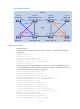
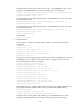
Dual homed rings configuration example
Networking requirements
As shown in Figure 26,
Router A through Router H form RRPP domain 1. Specify the primary control VLAN of RRPP
domain 1 as VLAN 4092, and specify that RRPP domain 1 protects VLANs 1 through 30.
Router A through Router D form primary ring 1. Router A, Router B, and Router E form subring 2.
Router A, Router B, and Router F form subring 3. Router C, Router D, and Router G form subring
4. Router C, Router D, and Router H form subring 5.
Specify Router A as the master node of primary ring 1, GigabitEthernet 3/0/1 as the primary
port and GigabitEthernet 3/0/2 as the secondary port. Specify Router E as the master node of
subring 2, GigabitEthernet 3/0/1 as the primary port and GigabitEthernet 3/0/2 as the
secondary port. Specify Router F as the master node of subring 3, GigabitEthernet 3/0/1 as the
primary port and GigabitEthernet 3/0/2 as the secondary port. Specify Router G as the master
node of subring 4, GigabitEthernet 3/0/1 as the primary port and GigabitEthernet 3/0/2 as
the secondary port. Specify Router H as the master node of subring 5, GigabitEthernet 3/0/1 as
the primary port and GigabitEthernet 3/0/2 as the secondary port.
Specify Router A as the edge node of the connected subrings, its GigabitEthernet 3/0/3 and
GigabitEthernet 3/0/4 as the edge ports. Specify Router D as the transit node of the primary
ring and edge node of the connected subrings, its GigabitEthernet 3/0/3 and GigabitEthernet
3/0/4 as the edge ports. Specify Router B and Router C as the transit node of the primary ring
and assistant-edge nodes of the connected subrings, their GigabitEthernet 3/0/3 and
GigabitEthernet 3/0/4 as the edge ports.
NOTE:
Configure the primary and secondary ports on the master nodes correctly to make sure that other
protocols still work correctly when data VLANs are denied by the secondary ports.