
R3102-R3103-HP 6600/HSR6600 Routers High Availability Configuration Guide
129
[RouterA] interface gigabitethernet 3/0/2
[RouterA-GigabitEthernet3/0/2] port link-type trunk
[RouterA-GigabitEthernet3/0/2] port trunk permit vlan 1 to 30
[RouterA-GigabitEthernet3/0/2] smart-link flush enable control-vlan 10 20
[RouterA-GigabitEthernet3/0/2] quit
6. Verify the configuration:
Use the display smart-link group command to display the smart link group configuration on a
device.
# Display the smart link group configuration on Router C.
[RouterC] display smart-link group 1
Smart link group 1 information:
Device ID: 000f-e23d-5af0
Preemption mode: NONE
Preemption delay: 1(s)
Control VLAN: 1
Protected VLAN: Reference Instance 1
Member Role State Flush-count Last-flush-time
-----------------------------------------------------------------------------
GigabitEthernet3/0/1 MASTER ACTVIE 5 16:37:20 2010/02/21
GigabitEthernet3/0/2 SLAVE STANDBY 1 17:45:20 2010/02/21
Use the display smart-link flush command to display the flush messages received on a device.
# Display the flush messages received on Router B.
[RouterB] display smart-link flush
Received flush packets : 5
Receiving interface of the last flush packet : GigabitEthernet3/0/3
Receiving time of the last flush packet : 16:25:21 2009/02/21
Device ID of the last flush packet : 000f-e23d-5af0
Control VLAN of the last flush packet : 1
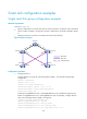
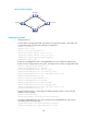
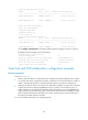
Multiple smart link groups load sharing configuration example
Network requirements
As shown in Figure 30:
Router C is a Smart Link device. Router A, Router B, and Router D are associated devices. Traffic
of VLANs 1 through 200 on Router C are dually uplinked to Router A by Router B and Router D.
Implement dual uplink backup and load sharing on Router C: Traffic of VLANs 1 through 100 is
uplinked to Router A by Router B. Traffic of VLANs 101 through 200 is uplinked to Router A by
Router D.