
R3102-R3103-HP 6600/HSR6600 Routers High Availability Configuration Guide

185
The output shows that when Router B fails, Router C becomes the master, and Forwarder 02 on
Router C immediately becomes active. Router C takes over the AVF on Router B.
IPv6-based VRRP configuration examples
Single VRRP group configuration example
Network requirements
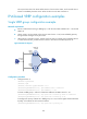
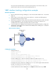
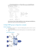
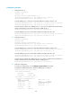
Router A and Router B belong to VRRP group 1 with the virtual IPv6 addresses of 1::10/64 and
FE80::10.
Host A wants to access Host B on the Internet. Host A learns 1::10/64 as its default gateway
through the RA messages sent by the routers.
When Router A operates correctly, packets sent from Host A to Host B are forwarded by Router
A. When Router A fails, packets sent from Host A to Host B are forwarded by Router B.
Figure 48 Network diagram
Configuration procedure
1. Configure Router A:
<RouterA> system-view
[RouterA] ipv6
[RouterA] interface gigabitethernet 1/0/1
[RouterA-GigabitEthernet1/0/1] ipv6 address fe80::1 link-local
[RouterA-GigabitEthernet1/0/1] ipv6 address 1::1 64
# Create a VRRP group 1 and set its virtual IPv6 addresses to FE80::10 and 1::10.
[RouterA-GigabitEthernet1/0/1] vrrp ipv6 vrid 1 virtual-ip fe80::10 link-local
[RouterA-GigabitEthernet1/0/1] vrrp ipv6 vrid 1 virtual-ip 1::10
# Configure the priority of Router A in VRRP group 1 as 110, which is higher than that of Router
B (100), so that Router A can become the master.
[RouterA-GigabitEthernet1/0/1] vrrp ipv6 vrid 1 priority 110
Host A
Router A
Router B
Virtual IPv6 address:
FE80::10
1::10/64
GE1/0/1
FE80::1
1::1/64
GE1/0/1
FE80::2
1::2/64
Host B
Gateway:
1::10/64
Internet