
R3102-R3103-HP 6600/HSR6600 Routers High Availability Configuration Guide

188
The output shows that after Router A resumes normal operation, it becomes the master, and
packets sent from Host A to Host B are forwarded by Router A.
VRRP interface tracking configuration example
Network requirements
Router A and Router B belong to VRRP group 1 with the virtual IPv6 addresses of 1::10/64 and
FE80::10.
Host A wants to access Host B on the Internet, and learns 1::10/64 as its default gateway
through RA messages sent by the routers.
When Router A operates correctly, Router A forwards the packets that Host A sends to Host B. If
interface GigabitEthernet 1/0/1 through which Router A connects to the Internet is not
available, Router B forwards the packets that Host A sends to Host B.
To prevent attacks to the VRRP group from illegal users by using spoofed packets, configure the
authentication mode as plain text to authenticate the VRRP packets in VRRP group 1. Specify the
authentication key as hello.
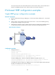
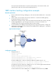
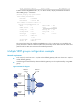
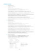
Figure 49 Network diagram
Configuration procedure
1. Configure Router A:
<RouterA> system-view
[RouterA] ipv6
[RouterA] interface gigabitethernet 1/0/2
[RouterA-GigabitEthernet1/0/2] ipv6 address fe80::1 link-local
[RouterA-GigabitEthernet1/0/2] ipv6 address 1::1 64
# Create a VRRP group 1 and set its virtual IPv6 addresses to FE80::10 and 1::10.
[RouterA-GigabitEthernet1/0/2] vrrp ipv6 vrid 1 virtual-ip fe80::10 link-local
[RouterA-GigabitEthernet1/0/2] vrrp ipv6 vrid 1 virtual-ip 1::10
# Configure the priority of Router A in VRRP group 1 as 110, which is higher than that of Router
B (100), so that Router A can become the master.
[RouterA-GigabitEthernet1/0/2] vrrp ipv6 vrid 1 priority 110
# Set the authentication mode of VRRP group 1 as simple and authentication key to hello.
Host A
Router A
Router B
Virtual IPv6 address:
FE80::10
1::10/64
GE1/0/2
FE80::1
1::1/64
GE1/0/2
FE80::2
1::2/64
Host B
Gateway:
1::10/64
GE1/0/1
Internet