
R3102-R3103-HP 6600/HSR6600 Routers High Availability Configuration Guide

194
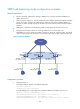
VRRP load balancing mode configuration example
Network requirements
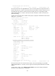
Router A, Router B, and Router C belong to VRRP group 1 with the virtual IPv6 addresses of
FE80::10 and 1::10.
Hosts on network segment 1::/64 learn FE80::10 as their default gateway through RA messages
sent by the routers. Configure the VRRP group to make sure that when a gateway (Router A,
Router B, or Router C) fails, the hosts on the LAN can access external networks through another
gateway.
VRRP group 1 operates in load balancing mode to make good use of network resources.
Configure a track entry on Router A, Router B, and Router C to monitor their own
GigabitEthernet 1/0/2. When the interface on Router A, Router B, or Router C fails, the weight
of the corresponding router decreases so that another router with a higher weight can take over.
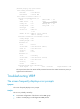
Figure 51 Network diagram
Configuration procedure
1. Configure Router A:
# Configure VRRP to operate in load balancing mode.
<RouterA> system-view
[RouterA] vrrp mode load-balance
# Create VRRP group 1 and configure its virtual IPv6 addresses as FE80::10 and 1::10.
[RouterA] interface gigabitethernet 1/0/1
[RouterA-GigabitEthernet1/0/1] ipv6 address fe80::1 link-local
[RouterA-GigabitEthernet1/0/1] ipv6 address 1::1 64
[RouterA-GigabitEthernet1/0/1] vrrp ipv6 vrid 1 virtual-ip fe80::10 link-local
Host A Host B Host C
Router A Router B Router C
GE1/0/1
IP: FE80::1; 1::1/64
VIP: FE80::10; 1::10
Network
GE1/0/1
IP: FE80::2; 1::2/64
VIP: FE80::10; 1::10
GE1/0/1
IP: FE80::3; 1::3/64
VIP: FE80::10; 1::10
Master
AVF 1
Backup
AVF 2
Backup
AVF 3
IP: 1::4/64
Gateway IP: 1::10
IP: 1::5/64
Gateway IP: 1::10
IP: 1::6/64
Gateway IP: 1::10
GE1/0/2
GE1/0/2
GE1/0/2