
R3102-R3103-HP 6600/HSR6600 Routers High Availability Configuration Guide


29
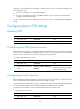
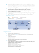
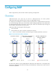
MD_A has three edge ports: GigabitEthernet 3/0/1 on Router A, GigabitEthernet 3/0/3 on
Router D, and GigabitEthernet 3/0/4 on Router E. They are all inward-facing MEPs. MD_B has
two edge ports: GigabitEthernet 3/0/3 on Router B and GigabitEthernet 3/0/1 on Router D.
They are both outward-facing MEPs.
In MD_A, Router B is designed to have MIPs when its port is configured with low level MEPs. Port
GigabitEthernet 3/0/3 is configured with MEPs of MD_B, and the MIPs of MD_A can be
configured on this port. Configure the MIP generation rule of MD_A as explicit.
The MIPs of MD_B are designed on Router C, and are configured on all ports. You should
configure the MIP generation rule as default.
Configure CC to monitor the connectivity among all the MEPs in MD_A and MD_B. Configure LB
to locate link faults.
After the status information of the entire network is obtained, use LT to detect link faults.
Figure 6 Network diagram
Configuration procedure
1. Configure a VLAN and assign ports to it:
On each device shown in Figure 6, create VLAN 100 and assign all ports to VLAN 100.
2. Enable CFD:
# Enable CFD on Router A.
<RouterA> system-view
[RouterA] cfd enable
Enable CFD on Router B through Router E using the same method.
3. Configure service instances:
# Create MD_A (level 5) on Router A, create MA_A, which serves VLAN 100, in MD_A, and
create service instance 1 for MD_A and MA_A.
[RouterA] cfd md MD_A level 5
[RouterA] cfd ma MA_A md MD_A vlan 100
[RouterA] cfd service-instance 1 md MD_A ma MA_A
Configure Router E as you configure Router A.
GE3/0/2
GE3/0/1 GE3/0/3
GE3/0/4
Router A
GE3/0/2
GE3/0/1 GE3/0/3
GE3/0/4
Router B
GE3/0/2
GE3/0/1 GE3/0/3
GE3/0/4
Router C
GE3/0/2
GE3/0/1 GE3/0/3
GE3/0/4
Router D
GE3/0/2
GE3/0/1 GE3/0/3
GE3/0/4
Router E
MD_A
MD_B
VLAN 100
Port Inward-facing MEP Outward-facing MEP
MIP with explicit rule MIP with default rule