
R3102-R3103-HP 6600/HSR6600 Routers High Availability Configuration Guide


92
4. Configure Router D:
Configure Router D by using the same procedure as for configuring Router B.
5. Verify the configuration:
Use the display command to view RRPP configuration and operational information on each
device.
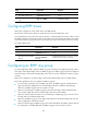
Intersecting ring configuration example
Networking requirements
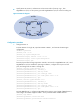
As shown in Figure 25,
Router A, Router B, Router C, Router D, and Router E form RRPP domain 1, VLAN 4092 is the
primary control VLAN of RRPP domain 1, and RRPP domain 1 protects VLANs 1 through 30.
Router A, Router B, Router C, and Router D form primary ring 1, and Router B, Router C and
Router E form subring 2.
Router A is the master node of primary ring 1, with GigabitEthernet 3/0/1 as the primary port
and GigabitEthernet 3/0/2 the secondary port.
Router E is the master node of subring 2, with GigabitEthernet 3/0/1 as the primary port and
GigabitEthernet 3/0/2 the secondary port.
Router B is the transit node of primary ring 1 and the edge node of subring 2, and
GigabitEthernet 3/0/3 is the edge port.
Router C is the transit node of primary ring 1 and the assistant-edge node of subring 1, and
GigabitEthernet 3/0/3 is the edge port.
Router D is the transit node of primary ring 1, with GigabitEthernet 3/0/1 as the primary port
and GigabitEthernet 3/0/2 the secondary port.
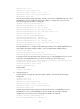
Figure 25 Network diagram
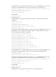
Configuration procedure
1. Configure Router A:
# Create VLANs 1 through 30, map these VLANs to MSTI 1, and activate the MST region
configuration.
<RouterA> system-view
Router A
Master node
Router D
Transit node
Domain 1
Ring 1
Router C
Assistant edge node
Router B
Edge node
Ring 2
Router E
Master node
GE3/0/1
GE3/0/1
GE3/0/1
GE3/0/1
GE3/0/1
GE3/0/2
GE3/0/2
GE3/0/2
GE3/0/2
GE3/0/2
GE3/0/3
GE3/0/3