
R3102-R3103-HP 6600/HSR6600 Routers Interface Command Reference

74
either the transmitting or receiving clock of the DCE device, so is the transmitting clock. Therefore,
five clock options are available for a DTE device.
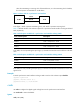
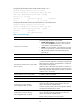
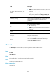
Figure 1 Select a clock for a synchronous serial interface
In the figure, "TxClk" represents transmitting clock, and "RxClk" represents receiving clock.
Table 14 de
scribe the four clock selection options for a synchronous serial interface working as DTE and
DCE, respectively.
Table 14 Clock options available for a synchronous serial interface working as DTE
Clock selection o
p
tion Descri
p
tion
DTEclk1 TxClk = TxClk, RxClk = RxClk.
DTEclk2 TxClk = TxClk, RxClk = TxClk.
DTEclk3 TxClk = RxClk, RxClk = TxClk.
DTEclk4 TxClk = RxClk, RxClk = RxClk.
In the table, the clock preceding the equal sign (=) is the DTE clock and the one that follows is the DCE
clock.
Table 15 Clock options available for a synchronous serial interface working as DCE
Clock selection o
p
tion Descri
p
tion
DCEclk1 TxClk = Local, RxClk = Local.
DCEclk2 TxClk = Local, RxClk = Line.
DCEclk3 TxClk = Line, RxClk = Line.
In the table, the clock preceding the equal sign (=) is the DCE clock and the one that follows is the clock
signal source.
Examples
# Set the synchronous serial interface working as DTE to use the clock selection option dteclk2.
<Sysname> system-view
[Sysname] interface serial 2/0/0
[Sysname-Serial2/0/0] clock dteclk2
code
Use code to configure the digital signal coding format on the synchronous serial interface.
Use undo code to restore the default.
Syntax
code { nrz | nrzi }