
R3102-R3103-HP 6600/HSR6600 Routers IP Multicast Configuration Guide
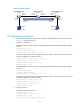
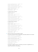
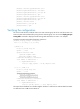
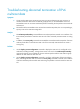
Table Of Contents
- Title Page
- Contents
- Multicast overview
- Configuring IGMP snooping
- Overview
- IGMP snooping configuration task list
- Configuring basic IGMP snooping functions
- Configuring IGMP snooping port functions
- Configuring IGMP snooping querier
- Configuring IGMP snooping proxying
- Configuring IGMP snooping policies
- Configuration prerequisites
- Configuring a multicast group filter
- Configuring multicast source port filtering
- Enabling dropping unknown multicast data
- Enabling IGMP report suppression
- Setting the maximum number of multicast groups that a port can join
- Enabling multicast group replacement
- Setting the 802.1p precedence for IGMP messages
- Enabling the IGMP snooping host tracking function
- Displaying and maintaining IGMP snooping
- IGMP snooping configuration examples
- Troubleshooting IGMP snooping
- Appendix
- Configuring multicast routing and forwarding
- Overview
- Configuration task list
- Enabling IP multicast routing
- Configuring multicast routing and forwarding
- Displaying and maintaining multicast routing and forwarding
- Configuration examples
- Troubleshooting multicast routing and forwarding
- Configuring IGMP
- Overview
- IGMP configuration task list
- Configuring basic IGMP functions
- Adjusting IGMP performance
- Configuring IGMP SSM mapping
- Configuring IGMP proxying
- Displaying and maintaining IGMP
- IGMP configuration examples
- Troubleshooting IGMP
- Configuring PIM
- Overview
- Configuring PIM-DM
- Configuring PIM-SM
- Configuring BIDIR-PIM
- Configuring PIM-SSM
- Configuring common PIM features
- Displaying and maintaining PIM
- PIM configuration examples
- Troubleshooting PIM
- Configuring MSDP
- Overview
- MSDP configuration task list
- Configuring basic MSDP functions
- Configuring an MSDP peer connection
- Configuring SA message related parameters
- Displaying and maintaining MSDP
- MSDP configuration examples
- Troubleshooting MSDP
- Configuring MBGP
- MBGP overview
- Protocols and standards
- MBGP configuration task list
- Configuring basic MBGP functions
- Controlling route advertisement and reception
- Configuration prerequisites
- Configuring MBGP route redistribution
- Configuring default route redistribution into MBGP
- Configuring MBGP route summarization
- Advertising a default route to an IPv4 MBGP peer or peer group
- Configuring outbound MBGP route filtering
- Configuring inbound MBGP route filtering
- Configuring MBGP route dampening
- Configuring MBGP route attributes
- Optimizing MBGP networks
- Configuring a large scale MBGP network
- Displaying and maintaining MBGP
- MBGP configuration example
- Configuring multicast VPN
- Overview
- How MD-VPN works
- Multicast VPN configuration task list
- Configuring MD-VPN
- Configuring BGP MDT
- Specifying the source IP address for multicast across VPNs
- Displaying and maintaining multicast VPN
- Multicast VPN configuration examples
- Troubleshooting MD-VPN
- Configuring IPv6 multicast routing and forwarding
- Overview
- Configuration task list
- Enabling IPv6 multicast routing
- Configuring IPv6 multicast routing and forwarding
- Displaying and maintaining IPv6 multicast routing and forwarding
- IPv6 multicast forwarding over GRE tunnel configuration example
- Troubleshooting abnormal termination of IPv6 multicast data
- Configuring MLD
- Overview
- MLD configuration task list
- Configuring basic MLD functions
- Adjusting MLD performance
- Configuring MLD SSM mapping
- Configuring MLD proxying
- Displaying and maintaining MLD
- MLD configuration examples
- Troubleshooting MLD
- Configuring IPv6 PIM
- Overview
- Configuring IPv6 PIM-DM
- Configuring IPv6 PIM-SM
- Configuring IPv6 BIDIR-PIM
- Configuring IPv6 PIM-SSM
- Configuring common IPv6 PIM features
- Displaying and maintaining IPv6 PIM
- IPv6 PIM configuration examples
- Troubleshooting IPv6 PIM
- Configuring IPv6 MBGP
- Overview
- IPv6 MBGP configuration task list
- Configuring basic IPv6 MBGP functions
- Controlling route distribution and reception
- Configuration prerequisites
- Injecting a local IPv6 MBGP route
- Configuring IPv6 MBGP route redistribution
- Configuring IPv6 MBGP route summarization
- Advertising a default route to a peer or peer group
- Configuring outbound IPv6 MBGP route filtering
- Configuring inbound IPv6 MBGP route filtering
- Configuring IPv6 MBGP route dampening
- Configuring IPv6 MBGP route attributes
- Optimizing IPv6 MBGP networks
- Configuring a large scale IPv6 MBGP network
- Displaying and maintaining IPv6 MBGP
- IPv6 MBGP configuration example
- Configuring PIM snooping
- Configuring multicast VLANs
- Support and other resources
- Index
275
Figure 78 Network diagram
Configuration procedure
1. Enable IPv6 forwarding and configure the IP address and prefix length for each interface as shown
in Figure 78. (Details not
shown.)
2. Configure a GRE tunnel:
# Create interface Tunnel 0 on Router A and assign the IPv6 address and prefix length to interface
Tunnel 0.
<RouterA> system-view
[RouterA] interface tunnel 0
[RouterA-Tunnel0] ipv6 address 5001::1 64
# On Router A, specify the tunnel encapsulation mode as GRE over IPv6 and assign the source and
destination addresses to interface Tunnel 0.
[RouterA-Tunnel0] tunnel-protocol gre ipv6
[RouterA-Tunnel0] source 2001::1
[RouterA-Tunnel0] destination 3001::2
[RouterA-Tunnel0] quit
# Create interface Tunnel 0 on Router C and assign the IPv6 address and prefix length to interface
Tunnel 0.
<RouterC> system-view
[RouterC] interface tunnel 0
[RouterC-Tunnel0] ipv6 address 5001::2 64
# On Router C, specify the tunnel encapsulation mode as GRE over IPv6 and assign the source and
destination addresses to interface Tunnel 0.
[RouterC-Tunnel0] tunnel-protocol gre
[RouterC-Tunnel0] source 3001::2
[RouterC-Tunnel0] destination 2001::1
[RouterC-Tunnel0] quit
3. Configure OSPFv3:
# Configure OSPFv3 on Router A.
[RouterA] ospfv3 1
[RouterA-ospfv3-1] router-id 1.1.1.1
[RouterA-ospfv3-1] quit
[RouterA] interface gigabitethernet 2/1/1
GE2/1/1
1001::1/64
IPv6 multicast router
Router A
GE2/1/2
2001::1/64
GE2/1/2
3001::1/64
GE2/1/2
3001::2/64
GE2/1/1
2001::2/64
Source Receiver
4001::100/64
GE2/1/1
4001::1/64
1001::100/64
GRE tunnel
Tunnel0
5001::1/64
Tunnel0
5001::2/64
IPv6 unicast router
Router B
IPv6 multicast router
Router C