
R3102-R3103-HP 6600/HSR6600 Routers Layer 2 - LAN Switching Configuration Guide

154
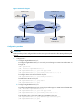
On third-party devices between PE 1 and PE 2, configure the port that connects to PE 1 and the
port that connects to PE 2 to allow tagged frames of VLAN 100 and VLAN 200 to pass through.
(Details not shown.)
Selective QinQ configuration example
Network requirements
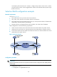
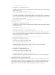
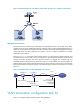
As shown in Figure 53:
• PE A and PE B are service provider network access devices.
• CE A, CE B, CE C, and CE D are customer network access devices.
• PE A and PE B are interconnected through a trunk port, which permits the frames of VLAN 1000,
VLAN 2000, and VLAN 3000 to pass through.
• Third-party devices are deployed between PE A and PE B, with a TPID value of 0x8200.
Make configurations to meet the following requirements:
• VLAN 10 of CE A and CE B can intercommunicate across VLAN 1000 on the public network.
• VLAN 20 of CE A and CE C can intercommunicate across VLAN 2000 on the public network.
• Frames of the VLANs other than VLAN 10 and VLAN 20 of CE A can be forwarded to CE D across
VLAN 3000 on the public network.
Figure 53 Network diagram
Configuration procedure
IMPORTANT:
Make sure that the devices in the service provider network have been confi
g
ured to allow QinQ packets to
pass through.
1. Configuration on PE A:
a. Configuration on GigabitEthernet 2/0/1: