
R3102-R3103-HP 6600/HSR6600 Routers Layer 2 - WAN Configuration Guide

19
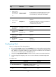
Task Command Remarks
Display information about PVC
mappings.
display atm map-info [ interface
interface-type interface-number [ pvc
{ pvc-name [ vpi/vci ] | vpi/vci } ] ] [ | { begin
| exclude | include } regular-expression ]
Available in any view.
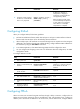
Display PVC-group information.
display atm pvc-group [ interface
interface-type interface-number [ pvc
{ pvc-name [ vpi/vci ] | vpi/vci } ] ] [ | { begin
| exclude | include } regular-expression ]
Available in any view.
Display information about an ATM
class.
display atm class [ atm-class-name ] [ | { begin
| exclude | include } regular-expression ]
Available in any view.
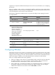
Send OAM cells on the specified
PVC on the interface to test
connectivity of the link depending
on whether response is returned
before the specified timeout time.
oamping interface atm interface-number pvc
{ pvc-name | vpi /vci } [ number timeout ]
Available in ATM
interface view.
Display information about Layer 3
VE interfaces.
display interface [ virtual-ethernet ] [ brief
[ down ] ] [ | { begin | exclude | include }
regular-expression ]
Available in any view.
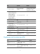
Clear the statistics of Layer 3 VE
interfaces.
reset counters interface [ virtual-ethernet
[ interface-number ] ]
Available in user view.
ATM configuration examples
This section provides ATM configuration examples.
IPoA configuration example
Network requirements
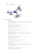
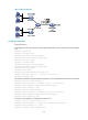
As shown in Figure 5, Router A, B, and C are connected to the ATM network for intercommunication.
The IP addresses of their ATM interfaces of the three routers are 202.38.160.1/24, 202.38.160.2/24,
and 202.38.160.3/24, respectively.
In the ATM network, the VPI/VCI of Router A is 0/40 and 0/41, connecting to Router B and Router C,
respectively. The VPI/VCI of Router B is 0/50 and 0/51, connecting to Router A and C, respectively. The
VPI/VCI of Router C is 0/60 and 0/61, connected with Router A and B, respectively.
All the PVCs on ATM interfaces of the three routers operate in IPoA application mode.