
R3102-R3103-HP 6600/HSR6600 Routers Layer 2 - WAN Configuration Guide

55
--- 200.1.1.1 ping statistics ---
5 packet(s) transmitted
5 packet(s) received
0.00% packet loss
round-trip min/avg/max = 1/4/10 ms
The output shows Serial 2/0/1 of Router A can be pinged.
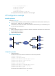
MP configuration example
Network requirements
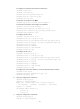
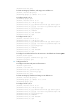
As shown in Figure 16:
• On an E1 interface of Router A, four channels are created with the interface names Serial 2/0/1:1,
Serial 2/0/1:2, Serial 2/0/1:3, and Serial 2/0/1:4.
• On Router B, two channels are created with the interface names Serial 2/0/1:1 and Serial 2/0/1:2.
It is the same case with Router C.
Do the following:
• Bind two channels on Router A with the two channels on Router B and another two channels with
the two channels on Router C.
• Adopt binding authentication.
Figure 16 Network diagram
Configuration procedure
1. Configure Router A:
# Create user accounts for Router B and Router C and set the passwords.
<RouterA> system-view
[RouterA] local-user router-b
[RouterA-luser-router-b] password simple router-b
[RouterA-luser-router-b] service-type ppp
[RouterA-luser-router-b] quit
[RouterA] local-user router-c
[RouterA-luser-router-c] password simple router-c
[RouterA-luser-router-c] service-type ppp
[RouterA-luser-router-c] quit
# Create two VT interfaces for the two user accounts.