
R3102-R3103-HP 6600/HSR6600 Routers Layer 3 - IP Routing Configuration Guide

114
Configuring OSPF NSR
Network requirements
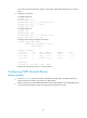
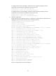
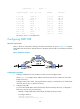
As shown in Figure 30, Router S, Router A, and Router B belong to the same OSPF routing domain.
Enable OSPF NSR on Router S to ensure correct routing when an active/standby switchover occurs on
Router S. Router S is an 6604, 6608, or 6616 router that has an RPE or RSE MPU installed.
Figure 30 Network diagram
Configuration procedure
1. Configure IP addresses for the interfaces on each router and configure OSPF:
Follow Figure 30 to c
onfigure the IP address and subnet mask of each interface on the routers.
(Details not shown.)
Configure OSPF on the routers, ensuring that Router S, Router A, and Router B can communicate
with each other at Layer 3 and dynamic route update can be implemented among them with OSPF.
(Details not shown.)
2. Configure OSPF NSR:
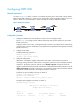
# Enable OSPF NSR on Router S.
<RouterS> system-view
[RouterS] ospf non-stop-routing
3. Verify the configuration:
After Router S establishes neighbor relationships with Router A and Router B, they start to
exchange routing information. After network convergence, perform an active/standby switchover
on Router S. During the switchover period, use the display ospf peer command to check the
neighbor relationships between Router A and Router S and between Router B and Router S; use the
display ospf routing command to check if there are routes from Router A to the loopback interface
on Router B and from Router B to the loopback interface on Router A.
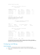
# Perform an active/standby switchover on Router S.
[RouterS] slave switchover enable
[RouterS] slave switchover
Caution!!! Confirm to swith slave to master? [Y/N]:y
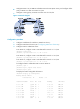
# Display OSPF neighbors and routes on Router A.
<RouterA> display ospf peer
OSPF Process 1 with Router ID 192.168.1.40
Neighbor Brief Information
Area: 0.0.0.0
Router ID Address Pri Dead-Time Interface State
192.168.1.41 12.12.12.2 1 40 GE2/1/1 Full/BDR