
R3102-R3103-HP 6600/HSR6600 Routers Layer 3 - IP Services Configuration Guide


280
# View tunnel entry information on Router A again. Because the branch has initiated tunnel
establishment by sending packets to the headquarters, a tunnel entry should be installed, as shown in the
following output information:
[RouterA] display gre p2mp tunnel-table interface tunnel 0
Dest Addr Mask Tunnel Dest Addr Gre Key
192.168.12.0 255.255.255.0 11.1.1.2
Configuration example for backing up a P2MP GRE
tunnel at the headquarters
Network requirements
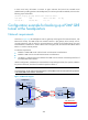
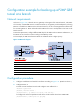
As shown in Figure 122, the headquarters uses two gateways at the egress of the internal network, with
Router B for backup. Two GRE tunnels are created on Router C (the gateway at the branch): one for
connecting Router A and the other for connecting Router B. Packets are forwarded along the tunnel
between Router A and Router C. When a failure occurs along this path, the tunnel between Router B and
Router C is used to transmit packets.
To meet the requirements:
• Establish a P2MP GRE tunnel with the branch on both Router A and Router B.
• Establish a GRE over IPv4 tunnel between Router A and Router B.
• On Router A, configure the tunnel interface of the GRE over IPv4 tunnel as the backup interface of
the P2MP GRE tunnel interface.
With this configuration, when Router A cannot find the corresponding tunnel entry for a packet, it delivers
the packet to Router B, which then forwards the packet to Router C.
NOTE:
To avoid looping, do not confi
g
ure the tunnel interface of the GRE over IPv4 tunnel as the backup interface
of the P2MP GRE tunnel interface on Router B.
Figure 122 Network diagram
GE3/1/2
GE3/1/1
GE3/1/1
Router A
Router B
(Backup gateway)
IPv4 network
Router C
GE3/1/2
GE3/1/3
GE3/1/3
GE3/1/1 GE3/1/2
Tunnel0
Tunnel0
Tunnel0
Tunnel1
Tunnel1
Tunnel1
Host A
Host B
Host C
GRE P2MP tunnel
GRE over IPv4 tunnel
Headquarters
Branch