
R3102-R3103-HP 6600/HSR6600 Routers MPLS Configuration Guide

132
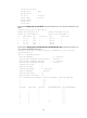
8. Create a static route to direct traffic destined for subnet 30.1.1.0/24 into the MPLS TE tunnel:
[RouterA] ip route-static 30.1.1.2 24 tunnel 1 preference 1
Execute the display ip routing-table command on Router A. The routing table has a static route
entry with interface Tunnel 1 as the outgoing interface.
MPLS LDP over MPLS TE configuration example
Network requirements
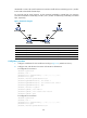
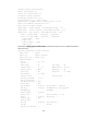
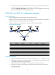
Router A through Router E all support MPLS and run OSPF as the IGP.
Establish a local LDP session between Router A and Router B, as well as between Router C and Router D.
Establish a remote LDP session between Router B and Router C.
Establish an MPLS TE tunnel along Router B—Router E—Router C by using RSVP-TE.
Figure 33 Network diagram
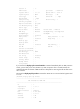
Device Interface IP address Device Interface IP address
Router A Loop0 1.1.1.1/32
Router E
Loop0
5.5.5.5/32
GE2/1/1 2.1.1.1/24
POS5/1/0 3.2.1.2/24
Router B Loop0 2.2.2.2/32 POS5/1/1 3.3.1.1/24
GE2/1/1 2.1.1.2/24
Router C
Loop0
3.3.3.3/32
GE2/1/2 3.1.1.1/24
GE2/1/1 4.1.1.1/24
POS5/1/0 3.2.1.1/24 GE2/1/2 3.1.1.2/24
Router D Loop0 4.4.4.4/32
POS5/1/1 3.3.1.2/24
GE2/1/1 4.1.1.2/24
Configuration procedure
1. Configure IP addresses and masks for the interfaces according to Figure 33. (Details not shown.)
2. Enable OSPF on each router to advertise subnets to which interfaces belong and the host routes
with LSR IDs as destinations. (Details not shown.)
3. Configure MPLS LDP basic settings on Router A and Router D. (Details not shown.)
4. Configure basic MPLS TE and enable RSVP-TE and CSPF on Router B, Router C and Router E:
# Configure Router B.
<RouterB> system-view