
R3102-R3103-HP 6600/HSR6600 Routers MPLS Configuration Guide
178
[Sysname] sysname PE2
[PE2] interface loopback 0
[PE2-LoopBack0] ip address 10.0.0.3 32
[PE2-LoopBack0] quit
[PE2] mpls lsr-id 10.0.0.3
[PE2] mpls
[PE2-mpls] quit
# Enable L2VPN and MPLS L2VPN.
[PE2] l2vpn
[PE2-l2vpn] mpls l2vpn
[PE2-l2vpn] quit
# Configure interface POS 5/1/1.
[PE2] interface pos 5/1/1
[PE2-POS5/1/1] link-protocol ppp
[PE2-POS5/1/1] quit
# Configure interface POS 5/1/0 and enable MPLS.
[PE2] interface pos 5/1/0
[PE2-POS5/1/0] link-protocol ppp
[PE2-POS5/1/0] ip address 10.2.2.1 24
[PE2-POS5/1/0] mpls
[PE2-POS5/1/0] quit
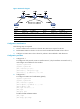
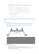
# Create a remote connection from CE 2 to CE 1, using the interface connected to CE 2 as the
incoming interface and that connecting the P device as the outgoing interface, setting the incoming
label to 201 and the outgoing label to 101.
[PE2] ccc ce2-ce1 interface pos 5/1/1 in-label 201 out-label 101 out-interface pos
5/1/0
5. Configure CE 2:
# Configure the link protocol as PPP on interface POS 5/1/0 (the interface connected to PE 2),
and configure an IP address for the interface.
<Sysname> system-view
[Sysname] sysname CE2
[CE2] interface pos 5/1/0
[CE2-POS5/1/0] link-protocol ppp
[CE2-POS5/1/0] ip address 100.1.1.2 24
6. Verify your configuration:
# Display CCC connection information on PE 1. The output shows that a remote CCC connection
has been established.
[PE1] display ccc
Total ccc vc : 1
Local ccc vc : 0, 0 up
Remote ccc vc : 1, 1 up
***Name : ce1-ce2
Type : remote
State : up
Intf : POS5/1/0 (up)
In-label : 100
Out-label : 200