
R3102-R3103-HP 6600/HSR6600 Routers MPLS Configuration Guide

230
[NPE3-l2vpn] mpls l2vpn
[NPE3-l2vpn] quit
# Create VPLS instance aaa that uses LDP signaling.
[NPE3] vsi aaa static
[NPE3-vsi-aaa] pwsignal ldp
[NPE3-vsi-aaa-ldp] vsi-id 500
[NPE3-vsi-aaa-ldp] peer 2.2.2.9
[NPE3-vsi-aaa-ldp] quit
[NPE3-vsi-aaa] quit
# Configure interface GigabitEthernet 2/1/1 and bind VPLS instance aaa to the interface.
[NPE3] interface gigabitethernet 2/1/1
[NPE3-GigabitEthernet2/1/1] l2 binding vsi aaa
[NPE3-GigabitEthernet2/1/1] quit
5. Verify the configuration:
Issue the display vpls connection command on the PEs. You can see that a PW connection in up
state has been established between the PEs.
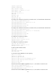
Configuring PW redundancy for H-VPLS access
Network requirements
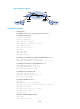
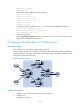
CE 1 and CE 2 are connected to the UPE through an Ethernet.
Establish a U-PW between UPE and NPE 1 and a backup U-PW between UPE and NPE 2. Establish an
N-PW between NPE 1 and NPE 3 and another N-PW between NPE 2 and NPE 3. Configure a VPLS
instance that supports H-VPLS network.
Figure 62 Network diagram
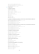
Configuration procedure
1. Configure an IGP on the MPLS backbone. (Details not shown.)
2. Configure UPE:
# Configure basic MPLS.