
R3102-R3103-HP 6600/HSR6600 Routers MPLS Configuration Guide
375
20.1.1.0/24 OSPF 10 1563 100.1.1.1 GE2/1/1
100.1.1.0/24 Direct 0 0 100.1.1.2 GE2/1/1
100.1.1.2/32 Direct 0 0 127.0.0.1 InLoop0
120.1.1.0/24 BGP 255 0 2.2.2.9 NULL0
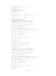
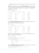
Execute the display ip routing-table command on the CEs, and you can see that the cost of the
OSPF route to the peer CE is now 10 (the cost configured for the sham link), and that the next hop
is now the Ethernet interface connected to the PE. This means that VPN traffic to the peer is
forwarded over the backbone. Take CE 1 as an example:
[CE1] display ip routing-table
Routing Tables: Public
Destinations : 9 Routes : 9
Destination/Mask Proto Pre Cost NextHop Interface
20.1.1.0/24 Direct 0 0 20.1.1.1 S2/1/2
20.1.1.1/32 Direct 0 0 127.0.0.1 InLoop0
20.1.1.2/32 Direct 0 0 20.1.1.2 S2/1/2
30.1.1.0/24 OSPF 10 1574 100.1.1.2 GE2/1/1
100.1.1.0/24 Direct 0 0 100.1.1.1 GE2/1/1
100.1.1.1/32 Direct 0 0 127.0.0.1 InLoop0
120.1.1.0/24 OSPF 10 12 100.1.1.2 GE2/1/1
127.0.0.0/8 Direct 0 0 127.0.0.1 InLoop0
127.0.0.1/32 Direct 0 0 127.0.0.1 InLoop0
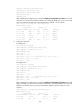
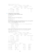
Execute the display ospf sham-link command on the PEs. The output shows that a sham link has
been established. Take PE 1 as an example:
[PE1] display ospf sham-link
OSPF Process 100 with Router ID 100.1.1.2
Sham Link:
Area NeighborId Source-IP Destination-IP State Cost
0.0.0.1 120.1.1.2 3.3.3.3 5.5.5.5 P-2-P 10
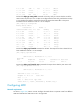
Execute the display ospf sham-link area command. The output shows that the peer state is Full:
[PE1] display ospf sham-link area 1
OSPF Process 100 with Router ID 100.1.1.2
Sham-Link: 3.3.3.3 --> 5.5.5.5
Neighbor ID: 120.1.1.2 State: Full
Area: 0.0.0.1
Cost: 10 State: P-2-P Type: Sham
Timers: Hello 10, Dead 40, Retransmit 5, Transmit Delay 1
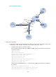
Configuring MCE
Network requirements
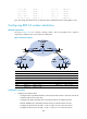
As shown in Figure 702, VPN 2 runs RIP. Configure the MCE device to separate routes from different
VPNs and advertise the VPN routes to PE 1 through OSPF.