
R3102-R3103-HP 6600/HSR6600 Routers MPLS Configuration Guide
32
Configuration procedure
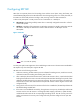
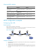
1. Configure IP addresses for the interfaces, according to Figure 13. (Details not shown.)
2. Configure a static route to the FEC destination address on each ingress node:
# Configure a static route to network 21.1.1.0/24 on Router A.
<RouterA> system-view
[RouterA] ip route-static 21.1.1.0 24 10.1.1.2
# Configure a static route to network 11.1.1.0/24 on Router C.
<RouterC> system-view
[RouterC] ip route-static 11.1.1.0 255.255.255.0 20.1.1.1
3. Enable MPLS:
# Configure MPLS on Router A.
[RouterA] mpls lsr-id 1.1.1.9
[RouterA] mpls
[RouterA-mpls] quit
[RouterA] interface serial 2/1/0
[RouterA-Serial2/1/0] mpls
[RouterA-Serial2/1/0] quit
# Configure MPLS on Router B.
[RouterB] mpls lsr-id 2.2.2.9
[RouterB] mpls
[RouterB-mpls] quit
[RouterB] interface serial 2/1/0
[RouterB-Serial2/1/0] mpls
[RouterB-Serial2/1/0] quit
[RouterB] interface serial 2/1/1
[RouterB-Serial2/1/1] mpls
[RouterB-Serial2/1/1] quit
# Configure MPLS on Router C.
[RouterC] mpls lsr-id 3.3.3.9
[RouterC] mpls
[RouterC-mpls] quit
[RouterC] interface serial 2/1/0
[RouterC-Serial2/1/0] mpls
[RouterC-Serial2/1/0] quit
4. Configure a static LSP from Router A to Router C:
# Configure the LSP ingress node, Router A.
[RouterA] static-lsp ingress AtoC destination 21.1.1.0 24 nexthop 10.1.1.2 out-label
30
# Configure the LSP transit node, Router B.
[RouterB] static-lsp transit AtoC incoming-interface serial 2/1/0 in-label 30 nexthop
20.1.1.2 out-label 50
# Configure the LSP egress node, Router C.
[RouterC] static-lsp egress AtoC incoming-interface serial 2/1/0 in-label 50
5. Create a static LSP from Router C to Router A:
# Configure the LSP ingress node, Router C.