
R3303-HP 6600/HSR6600 Routers MPLS Configuration Guide

179
[CE1] ping 100.1.1.2
PING 100.1.1.2: 56 data bytes, press CTRL_C to break
Reply from 100.1.1.2: bytes=56 Sequence=1 ttl=255 time=180 ms
Reply from 100.1.1.2: bytes=56 Sequence=2 ttl=255 time=60 ms
Reply from 100.1.1.2: bytes=56 Sequence=3 ttl=255 time=10 ms
Reply from 100.1.1.2: bytes=56 Sequence=4 ttl=255 time=70 ms
Reply from 100.1.1.2: bytes=56 Sequence=5 ttl=255 time=60 ms
--- 100.1.1.2 ping statistics ---
5 packet(s) transmitted
5 packet(s) received
0.00% packet loss
round-trip min/avg/max = 10/76/180 ms
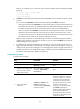
Example for configuring a remote CCC connection
Network requirements
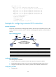
The CEs are connected to the PEs through POS interfaces. The link layer encapsulation protocol is PPP.
Create a remote CCC connection, so CE 1 and CE 2 can exchange Layer 2 packets across the backbone
network.
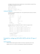
Figure 46 Network diagram
Device Interface IP address Device Interface IP address
CE 1 POS5/1/0 100.1.1.1/24
CE 2
POS5/1/0 100.1.1.2/24
PE 1 Loop0 10.0.0.1/32
P
Loop0
10.0.0.2/32
POS5/1/1 10.1.1.1/24 POS5/1/0 10.2.2.2/24
PE 2 Loop0 10.0.0.3/32
POS5/1/1 10.1.1.2/24
POS5/1/0 10.2.2.1/24
Configuration considerations
The following steps are required:
1. Create a remote CCC connection on the PEs. No static LSP is required on the PEs.
2. Enable MPLS L2VPN on the PEs. You do not need to enable MPLS L2VPN on the P device.
3. Configure two static LSPs on the P device for packets to be transferred in both directions.
Configuration procedure
1. Configure CE 1: