
R3303-HP 6600/HSR6600 Routers MPLS Configuration Guide


391
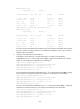
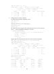
10.2.1.0/24 Direct 0 0 10.2.1.1 GE2/1/1
10.2.1.1/32 Direct 0 0 127.0.0.1 InLoop0
10.3.1.0/24 BGP 255 0 10.2.1.2 GE2/1/1
10.3.1.1/32 BGP 255 0 10.2.1.2 GE2/1/1
127.0.0.0/8 Direct 0 0 127.0.0.1 InLoop0
127.0.0.1/32 Direct 0 0 127.0.0.1 InLoop0
200.1.1.1/32 BGP 255 0 10.2.1.2 GE2/1/1
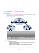
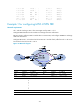
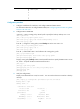
Example 1 for configuring MPLS L3VPN FRR
Network requirements
CE 1 and CE 2 belong to VPN 1. The route target used by VPN 1 is 111:1.
Configure EBGP between the CEs and PEs to exchange VPN route information.
Between the PEs, configure OSPF to enable them to communicate, and configure MP-IBGP to exchange
VPN route information.
Configure FRR on PE 1 so that when the link between PE 1 and PE 2 fails, traffic from CE 1 to CE 2 can
be switched to the link from PE 1 to PE 3.
Figure 101 Network diagram
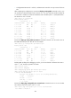
Device Interface IP address
Device
Interface
IP address
CE 1 GE2/1/1 10.2.1.1/24
PE 1
Loop0
1.1.1.1/32
PE 2 Loop0 2.2.2.2/32 GE2/1/1 10.2.1.2/24
GE2/1/1 172.1.1.2/24
GE2/1/2 172.1.1.1/24
G
E
2
/
1
/
2
10.1.1.2/24 GE2/1/3 172.2.1.1/24
PE 3 Loop0 3.3.3.3/32 CE 2 Loop0 4.4.4.4/32
GE2/1/1 172.2.1.2/24
GE2/1/1 10.1.1.1/24