HP 6600/HSR6600 Routers High Availability Configuration Guide Part number: 5998-1495 Software version: A6602-CMW520-R3103 A6600-CMW520-R3102-RPE A6600-CMW520-R3102-RSE HSR6602_MCP-CMW520-R3102 Document version: 6PW103-20130628
Legal and notice information © Copyright 2013 Hewlett-Packard Development Company, L.P. No part of this documentation may be reproduced or transmitted in any form or by any means without prior written consent of Hewlett-Packard Development Company, L.P. The information contained herein is subject to change without notice.
Contents High availability overview ·············································································································································· 1 Availability requirements ·················································································································································· 1 Availability evaluation ····································································································································
Configuring MEPs ·················································································································································· 25 Configuring MIP generation rules ························································································································ 25 Configuring CFD functions ············································································································································ 26 Configuration prer
Configuring the ATD timer ···································································································································· 66 Configuring the hold off timer ······························································································································ 66 Configuring the keepalive timer··························································································································· 67 Configuring the topology stabil
Enabling the receiving of flush messages ········································································································· 124 Displaying and maintaining Smart Link ····················································································································· 124 Smart Link configuration examples····························································································································· 125 Single smart link group configuration
Stateful failover configuration example ····················································································································· 207 Configuration guidelines ············································································································································· 208 Configuring BFD·························································································································································· 209 Intr
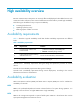
High availability overview Because communication interruptions can seriously affect widely-deployed value-added services such as IPTV and video conference, basic network infrastructures must be able to provide high availability. The following are the effective ways to improve availability: Increasing fault tolerance. Speeding up fault recovery. Reducing impact of faults on services.
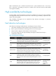
MTTR = fault detection time + hardware replacement time + system initialization time + link recovery time + routing time + forwarding recovery time. A smaller value of each item means a smaller MTTR and a higher availability. High availability technologies Increasing MTBF or decreasing MTTR can enhance the availability of a network. The high availability technologies described in this section meet the level 2 and level 3 high availability requirements in the aspect of decreasing MTTR.
Technology Introduction Reference Track The Track module implements collaboration between different modules. The collaboration involves three sets of modules: application, Track, and detection. These modules collaborate with one another through collaboration entries. The detection modules trigger the application modules to perform certain operations through the Track module.
Technology Introduction Reference RPR RPR is a new MAC layer protocol designed for transferring mass data services over MANs. It can operate on SONET/SDH, DWDM and Ethernet to provide flexible and efficient networking schemes for broadband IP MANs carriers. "Configuring RPR" RRPP RRPP is a link layer protocol designed for Ethernet rings.
Configuring active and standby switchover This feature is supported only by 6604/6608/6616 routers. If a device has two MPUs, the MPU that forwards and processes packets is called the active MPU, and the MPU that is in the standby state is called the standby MPU. The system uses the main board with a smaller slot number as the active MPU, and the other main board as the standby MPU. The standby MPU keeps its configuration the same as the active MPU through the synchronization function.
Ignoring version check of the standby MPU When the standby MPU attempts to start up, the system by default examines its software version against the software version on the active MPU for inconsistency. If the versions of the active MPU and standby MPU are not consistent, the standby MPU cannot be started. To disable the system from examining the software version of the standby MPU: Step Command Remarks 1. Enter system view. system-view N/A 2. Ignore version check of the standby MPU.
Displaying and maintaining active and standby switchover Task Command Remarks Display the switchover state of MPUs. display switchover state [ slot slot-number ] [ | { begin | exclude | include } regular-expression ] Available in any view.
Configuring Ethernet OAM Ethernet OAM is supported only when the SAP module is operating in bridge mode. Overview Ethernet Operation, Administration and Maintenance (OAM) is a tool that monitors Layer 2 link status and addresses common link-related issues on the "last mile." Ethernet OAM improves Ethernet management and maintainability. You can use it to monitor the status of the point-to-point link between two directly connected devices.
Table 4 Fields in an OAMPDU Field Description Destination MAC address of the Ethernet OAMPDU. Dest addr Source addr Type Subtype It is a slow protocol multicast address 0180c2000002. Because bridges cannot forward slow protocol packets, Ethernet OAMPDUs cannot be forwarded. Source MAC address of the Ethernet OAMPDU. It is the bridge MAC address of the sending side and is a unicast MAC address. Type of the encapsulated protocol in the Ethernet OAMPDU. The value is 0x8809.
IMPORTANT: To set up an OAM connection between two OAM entities, you must set at least one entity to operate in active mode. Table 6 shows the actions that a device can perform in different modes.
The system transforms the period of detecting errored frame period events into the maximum number of 64-byte frames that a port can send in the specified period. The system takes the maximum number of frames sent as the period. The maximum number of frames sent is calculated using this formula: Maximum number of frames = interface bandwidth (bps) × errored frame period event detection period (in ms)/(64 × 8 × 1000) The second in which errored frames appear is called an "errored frame second.
Task Remarks Configuring the Ethernet OAM connection detection timers Required Configuring link monitoring Configuring Ethernet OAM remote loopback Configuring errored symbol event detection Optional Configuring errored frame event detection Optional Configuring errored frame period event detection Optional Configuring errored frame seconds event detection Optional Enabling Ethernet OAM remote loopback in user view Optional Enabling Ethernet OAM remote loopback in system view Optional Enab
After the timeout timer of an Ethernet OAM connection expires, the local OAM entity ages out its connection with the peer OAM entity, causing the OAM connection to disconnect. HP recommends that you set the connection timeout timer at least five times the handshake packet transmission interval, ensuring the stability of Ethernet OAM connections. To configure the Ethernet OAM connection detection timers: Step Command Remarks N/A 1. Enter system view. system-view 2.
Step 2. 3. Command Remarks Configure the errored frame event detection interval. oam errored-frame period period-value Configure the errored frame event triggering threshold. oam errored-frame threshold threshold-value Optional. 1 second by default. Optional. 1 by default. Configuring errored frame period event detection An errored frame period event occurs if the number of frame errors in a specific number of received frames exceeds the predefined threshold.
CAUTION: The Ethernet OAM remote loopback function can impact other services. Use it with caution. When you enable Ethernet OAM remote loopback on a port, the port sends Loopback Control OAMPDUs to a remote port, and the remote port enters the loopback state. The port then sends test frames to the remote port. By observing how many of these test frames return, you can calculate the packet loss ratio on the link and evaluate the link performance.
Step 2. Enable Ethernet OAM remote loopback on a specific port. Command Remarks oam loopback interface interface-type interface-number Disabled by default. Enabling Ethernet OAM remote loopback in Ethernet port view Step Command Remarks 1. Enter system view. system-view N/A 2. Enter Ethernet port view. interface interface-type interface-number N/A 3. Enable Ethernet OAM remote loopback on the port. oam loopback Disabled by default.
Task Command Remarks Display the statistics on critical events after an Ethernet OAM connection is established. display oam critical-event [ interface interface-type interface-number ] [ | { begin | exclude | include } regular-expression ] Available in any view. Display the statistics on Ethernet OAM link error events after an Ethernet OAM connection is established.
# Set the errored frame detection interval to 20 seconds and set the errored frame event triggering threshold to 10. [RouterA] oam errored-frame period 20 [RouterA] oam errored-frame threshold 10 2. Configure Router B: # Configure GigabitEthernet 3/0/1 to operate in active Ethernet OAM mode (the default) and enable Ethernet OAM for it.
# Display Ethernet OAM link event statistics of the remote end of Router B.
Configuring CFD CFD is supported only when the SAP module is operating in bridge mode. Overview Connectivity Fault Detection (CFD) is an end-to-end per-VLAN link layer OAM mechanism used for link connectivity detection, fault verification, and fault location. It conforms to IEEE 802.1ag CFM. Basic CFD concepts Maintenance domain A maintenance domain (MD) defines the network or part of the network where CFD plays its role. An MD is identified by its MD name.
An MA serves a VLAN. Packets sent by the MPs in an MA carry the relevant VLAN tag. An MP can receive packets sent by other MPs in the same MA. The level of an MA equals the level of the MD that the MA belongs to. Maintenance point An MP is configured on a port and belongs to an MA. MPs include two types: maintenance association end points (MEPs) and maintenance association intermediate points (MIPs). MEP MEPs define the boundary of the MA. Each MEP is identified by a MEP ID.
configured on the ports of Router A through Router F. Port 1 of Router B is configured with the following MPs—a level 5 MIP, a level 3 inward-facing MEP, a level 2 inward-facing MEP, and a level 0 outward-facing MEP.
LB Similar to ping at the IP layer, loopback verifies the connectivity between a source device and a target device. To implement this function, the source MEP sends loopback messages (LBMs) to the target MEP. Depending on whether the source MEP can receive a loopback reply message (LBR) from the target MEP, the link state between the two can be verified. LBM frames and LBR frames are unicast frames. LT Linktrace is similar to traceroute. It identifies the path between the source MEP and the target MEP.
Typically, a port blocked by the spanning tree feature cannot receive or send CFD messages except in the following cases: The port is configured as an outward-facing MEP. The port is configured as a MIP or inward-facing MEP, which can still receive and send CFD messages except CCM messages. For more information about the spanning tree feature, see Layer 2—LAN Switching Configuration Guide. Configuring basic CFD settings Enabling CFD Step Command Remarks 1. Enter system view.
Step Command Remarks 2. Create an MD. cfd md md-name level level-value Not created by default. 3. Create an MA. cfd ma ma-name md md-name vlan vlan-id Not created by default. 4. Create a service instance. cfd service-instance instance-id md md-name ma ma-name Not created by default. Configuring MEPs CFD is implemented through various operations on MEPs. As a MEP is configured on a service instance, the MD level and VLAN attribute of the service instance become the attribute of the MEP.
Enabling CFD (use the cfd enable command). Creating or deleting the MEPs on a port. Changes occur to the VLAN attribute of a port. The rule specified in the cfd mip-rule command changes. Configuring CFD functions Configuration prerequisites Complete basic CFD settings. Configuring CC on MEPs You must configure CC before configuring other CFD functions. After the CC function is configured, MEPs can send CCM frames to one another to check the connectivity between them.
Step Command Remarks Configure the interval field value in the CCM messages sent by MEPs. cfd cc interval interval-value service-instance instance-id Optional. 3. Enter Ethernet interface view. interface interface-type interface-number N/A 4. Enable CCM sending on a MEP. cfd cc service-instance instance-id mep mep-id enable Disabled by default. 2. By default, the interval field value is 4.
Displaying and maintaining CFD Task Command Remarks Display CFD status. display cfd status [ | { begin | exclude | include } regular-expression ] Available in any view. Display the CFD protocol version. display cfd version [ | { begin | exclude | include } regular-expression ] Available in any view. Display MD configuration information. display cfd md [ | { begin | exclude | include } regular-expression ] Available in any view. Display MA configuration information.
MD_A has three edge ports: GigabitEthernet 3/0/1 on Router A, GigabitEthernet 3/0/3 on Router D, and GigabitEthernet 3/0/4 on Router E. They are all inward-facing MEPs. MD_B has two edge ports: GigabitEthernet 3/0/3 on Router B and GigabitEthernet 3/0/1 on Router D. They are both outward-facing MEPs. In MD_A, Router B is designed to have MIPs when its port is configured with low level MEPs.
# Create MD_A (level 5) on Router B, create MA_A, which serves VLAN 100, in MD_A, and then create service instance 1 for MD_A and MA_A. In addition, create MD_B (level 3) and MA_B that serves VLAN 100, in MD_B, and then create service instance 2 for MD_B and MA_B.
[RouterE] interface gigabitethernet 3/0/4 [RouterE-GigabitEthernet3/0/4] cfd mep 5001 service-instance 1 inbound [RouterE-GigabitEthernet3/0/4] cfd mep service-instance 1 mep 5001 enable [RouterE-GigabitEthernet3/0/4] quit 5. Configure MIP generation rules: # Configure the MIP generation rule in service instance 1 on Router B as explicit. [RouterB] cfd mip-rule explicit service-instance 1 # Configure the MIP generation rule in service instance 2 on Router C as default.
Send:5 Received:5 Lost:0 After the whole network status is obtained with the CC function, use the LT function to identify the paths between source and target MEPs, and to locate faults. 2. Verify the LT function: # Identify the path between MEP 1001 and MEP 5001 in service instance 1 on Router A.
Configuring DLDP DLDP is supported only when the SAP module is operating in bridge mode. Overview Unidirectional links occur when only one end of a bidirectional link can receive packets. Unidirectional links cause problems such as loops in an STP-enabled network. For example, the link between two switches, Switch A and Switch B, is a bidirectional link when they are connected through a fiber pair, with one fiber used for sending packets from A to B and the other for sending packets from B to A.
As a data link layer protocol, DLDP cooperates with physical layer protocols to monitor link status. When the auto-negotiation mechanism provided by the physical layer detects physical signals and faults, DLDP performs operations such as identifying peer devices, detecting unidirectional links, and shutting down unreachable ports.
DLDP timer Description Advertisement timer Determines the interval for sending common advertisement packets (default is 5 seconds). Probe timer Determines the interval for sending Probe packets (default is 1 second). By default, a device in the probe state sends one Probe packet every second. The maximum number of Probe packets that can be sent successively is 10. Echo timer This timer is set to 10 seconds.
per second. If no Echo packet has been received from the neighbor when the Echo timer expires, the device transits to the Disable state. Table 12 shows the relationship between the DLDP modes and neighbor entry aging.
DLDP authentication mode You can use DLDP authentication to prevent network attacks and illegal detecting. The following DLDP authentication modes are available: Non-authentication: The sending side sets the Authentication field and the Authentication type field of DLDP packets to 0. The receiving side checks the values of the two fields of received DLDP packets and drops packets where the two fields conflict with the corresponding local configuration.
Table 15 Processing incoming DLDP packets by packet type Packet type Advertisement with RSY tag Processing procedure Retrieves the neighbor information. Normal Advertisement Retrieves the neighbor information. Flush packet Checks whether the local DLDP port state is Disable. Probe Retrieves the neighbor information. If no matching neighbor entry exists, creates the neighbor entry, triggers the Entry timer, and changes the DLDP port state to Probe.
Packet type Processing procedure If yes and the local port is not in Disable state, sets the state of the neighbor to one way, and then checks the state of other neighbors to determine the subsequent action to take: LinkDown packet Checks whether the local port operates in Enhanced mode. If all the neighbors are in one way state, changes the local DLDP port state to Disable. If the state of some neighbors is still unknown, takes no action until the state of these neighbors is determined.
DLDP neighbor state A DLDP neighbor can be in one of the three states described in Table 17. Table 17 DLDP neighbor states DLDP neighbor state Description Unknown A neighbor is in this state when it is just detected and is being probed. A neighbor is in this state only when it is being probed. It transits to Two way state or Unidirectional state after the probe operation finishes. Two way A neighbor is in this state after it receives response from its peer.
Step Command Remarks 1. Enter system view. system-view N/A 2. Enter Ethernet interface view. interface interface-type interface-number N/A Optional. 3. Set the duplex mode. By default, the duplex mode is auto for Ethernet interfaces. duplex full For more information about command, see Interface Command Reference. Optional. 4. Set the port speed. speed { 10 | 100 | 1000 | 10000 } By default, the port speed is automatically negotiated.
In enhanced mode, DLDP actively detects neighbors when the corresponding neighbor entries age out. To set DLDP mode: Step Command Remarks N/A 1. Enter system view. system-view 2. Set DLDP mode. dldp work-mode { enhance | normal } Optional. Normal by default. Setting the interval to send advertisement packets DLDP detects unidirectional links by sending Advertisement packets.
Setting the port shutdown mode On detecting a unidirectional link, the ports can be shut down in one of the following two modes. Manual mode—This mode applies to low performance networks, where normal links might be treated as unidirectional links. It protects data traffic transmission against false unidirectional links. In this mode, DLDP only detects unidirectional links but does not automatically shut down unidirectional link ports.
Resetting DLDP state After DLDP detects a unidirectional link on a port, the port enters Disable state. In this case, DLDP prompts you to shut down the port manually, or it shuts down the port automatically depending on the user-defined port shutdown mode. To enable the port to perform DLDP detect again, you can reset the DLDP state of the port by using one of the following methods: If the port is shut down with the shutdown command manually, run the undo shutdown command on the port.
Displaying and maintaining DLDP Task Command Remarks Display the DLDP configuration of a port. display dldp [ interface-type interface-number ] [ | { begin | exclude | include } regular-expression ] Available in any view. Display the statistics on DLDP packets passing through a port. display dldp statistics [ interface-type interface-number ] [ | { begin | exclude | include } regular-expression ] Available in any view. Clear the statistics on DLDP packets passing through a port.
Configuration procedure 1. Configure Router A: # Enable DLDP globally. system-view [RouterA] dldp enable # Configure GigabitEthernet 3/0/1 to operate in full duplex mode and at 1000 Mbps, and enable DLDP on the port.
3. Verify the configuration: After the configurations are complete, you can use the display dldp command to display the DLDP configuration information on ports. # Display the DLDP configuration information on all the DLDP-enabled ports of Router A. [RouterA] display dldp DLDP global status : enable DLDP interval : 5s DLDP work-mode : enhance DLDP authentication-mode : none DLDP unidirectional-shutdown : auto DLDP delaydown-timer : 1s The number of enabled ports is 2.
malfunction in the Tx direction or cross-connected links exist between the local device and its neighbor. The shutdown mode is AUTO. DLDP shuts down the port. #Jan 18 17:36:20:189 2010 RouterA DLDP/1/TrapOfUnidirectional: -Slot=2; Trap 1.3.6.1.4.1.255062.43.2.1.1 : DLDP detects a unidirectional link in port 17825793. %Jan 18 17:36:20:189 2010 RouterA IFNET/3/LINK_UPDOWN: GigabitEthernet3/0/2 link status is DOWN.
Figure 10 Network diagram Correct fiber connection Cross-connected fibers Router A Router A GE3/0/1 GE3/0/2 GE3/0/1 GE3/0/2 GE3/0/1 GE3/0/2 GE3/0/1 GE3/0/2 Router B Ethernet fiber port Router B Tx end Rx end Fiber link Configuration procedure 1. Configure Router A: # Enable DLDP globally. system-view [RouterA] dldp enable # Configure GigabitEthernet 3/0/1 to operate in full duplex mode and at 1000 Mbps, and enable DLDP on the port.
# Enable DLDP globally. system-view [RouterB] dldp enable # Configure GigabitEthernet 3/0/1 to operate in full duplex mode and at 1000 Mbps, and enable DLDP on it. [RouterB] interface gigabitethernet 3/0/1 [RouterB-GigabitEthernet3/0/1] duplex full [RouterB-GigabitEthernet3/0/1] speed 1000 [RouterB-GigabitEthernet3/0/1] dldp enable [RouterB-GigabitEthernet3/0/1] quit # Configure GigabitEthernet 3/0/2 to operate in full duplex mode and at 1000 Mbps, and enable DLDP on it.
Neighbor mac address : 0023-8956-3600 Neighbor port index : 60 Neighbor state : two way Neighbor aged time : 12 The output indicates that both GigabitEthernet 3/0/1 and GigabitEthernet 3/0/2 are in Advertisement state, which means both links are bidirectional. # Enable system information monitoring on Router A, and enable the display of log and trap information.
[RouterA-GigabitEthernet3/0/2] undo shutdown [RouterA-GigabitEthernet3/0/2] %Jan 18 18:22:11:698 2010 RouterA IFNET/3/LINK_UPDOWN: GigabitEthernet3/0/2 link status is UP. [RouterA-GigabitEthernet3/0/2] quit [RouterA] interface gigabitethernet 3/0/1 [RouterA-GigabitEthernet3/0/1] undo shutdown [RouterA-GigabitEthernet3/0/1] %Jan 18 18:22:46:065 2010 RouterA IFNET/3/LINK_UPDOWN: GigabitEthernet3/0/1 link status is UP.
Configuring RPR RPR overview Resilient Packet Ring (RPR) is a new MAC layer protocol designed for transferring mass data services over MANs. It can operate on synchronous optical network/synchronous digital hierarchy (SONET/SDH), Dense Wavelength Division Multiplexing (DWDM) and Ethernet to provide flexible and efficient networking schemes for broadband IP MANs carriers. The RPR technology delivers these benefits: Physical layer diversity. High bandwidth utilization.
stations form a domain. A span on which data frames are not allowed to pass is called an "edge." If a ring contains at least one detected edge, it is called "open ring." If it does not contain any detected edges, it is called "closed ring." Data operations on RPR Stations on an RPR handle data frames by performing the following four types of operations: Insert, to place a frame on a ringlet. Transit, to pass a frame to the next station.
Broadcast, multicast, and unknown unicast transmission Figure 13 Broadcast, multicast, and unknown unicast transmission on an RPR ring Copy from ringlet 0 Insert to ringlet 0 Strip Copy from ringlet 0 Copy from ringlet 0 Copy from ringlet 0 Figure 13 shows how a broadcast, multicast, or unknown unicast frame is transmitted on an RPR ringlet: 1. The source station inserts the frame into the data stream on Ringlet 0 or Ringlet 1. 2.
ATD frames convey attributes of the local station such as the MAC address and station name. These attributes will be included in the topology database. TC frames convey topology checksum information. They are sent between adjacent stations to check whether the topology databases on them are synchronized, identifying stability of the RPR ring topology. All these control frames are sent at regular intervals, which are user configurable.
Figure 14 Schematic diagram before and after protection switchover Station B Station A Station C Link failure Ringlet 0 Ringlet 1 Data transmission path Station E Station D Data transmission before protection switchover Station B Station A Station E Station B Station C Station A Station D Station E Data transmission after protection switchover (wrapping mode) Station C Station D Data transmission after protection switchover (steering mode) As shown in Figure 14, traffic travels from station
Protection switching occurs only when requested by a station on the ring. The hierarchy of protection requests is the same as this protection switching hierarchy. Among protection requests, FS and MS requests are sent manually, whereas SF, SD, and WTR requests are sent automatically. If multiple protection requests appear at the same time, the higher priority protection request is processed preferentially.
For an RPR station to work, you must bind its RPR logical interface with at least one RPR physical port. With only one RPR physical port, the station is working in protection mode. For the RPR station to forward traffic, before binding two RPR physical ports with the same RPR logical interface, you must connect their mate ports. You can bind any type of RPR physical ports to an RPR logical interface. However, the RPR physical ports bound to a logical RPR interface must be of the same type.
Task Remarks Configuring the hold off timer Optional Configuring the keepalive timer Optional Configuring the topology stability timer Optional Configuring the TC timers Optional Configuring the TP timers Optional Configuring the WTR timer Optional Testing connectivity between RPR stations Optional Configuring basic RPR functions Configuring an RPR physical port To configure an RPRPOS interface: Step Command Remarks 1. Enter system view. system-view N/A 2.
Step Command Remarks Optional. 8. 9. Set the actions that the interface performs for an alarm. alarm-detect { rdi | sd | sf } action link-down Set the maximum available bandwidth for the interface. bandwidth bandwidth-value 10. Shut down the interface. shutdown 11. Restore the default settings of the interface. default By default, the interface does not perform any action for an alarm. Support for the command depends on the device model. Optional. Optional. Enabled by default. Optional.
Binding RPR physical ports with an RPR logical interface in RPR logical interface view Step Command Remarks 1. Enter system view. system-view N/A 2. Enter RPR logical interface view. interface rpr interface-number N/A 3. Bind an RPR physical port with the RPR logical interface. rpr bind { rprpos interface-number } { ringlet0 | ringlet1 } By default, no RPR physical ports are bound with an RPR logical interface.
Step 3. Configure a station name. Command Remarks rpr station-name station-name No station name is configured by default. Configuring RPR protection Configuring the RPR protection mode All the stations on an RPR ring must adopt the same protection mode for the ring to operate correctly. To configure the protection mode on the RPR station: Step Command Remarks 1. Enter system view. system-view N/A 2. Enter RPR logical interface view. interface rpr interface-number N/A 3.
Step Command 1. Enter system view. system-view 2. Enter RPR logical interface view. interface rpr interface-number 3. Send an RPR protection request on a ringlet. rpr admin-request { fs | ms | idle } { ringlet0 | ringlet1 } Configuring the ringlet selection table Each RPR station maintains a ringlet selection table for making ringlet selection decisions for frame transmission.
Configuring default ringlet selection Step Command Remarks 1. Enter system view. system-view N/A 2. Enter RPR logical interface view. interface rpr interface-number N/A 3. Configure default ringlet selection. Optional. rpr default-rs { ringlet0 | ringlet1 } By default, the default ringlet is Ringlet 0. NOTE: When a span is faulty and unable to forward data on the default ringlet configured, another ringlet works as the default ringlet.
NOTE: The total bandwidth reserved for subclass A0 by the stations on a ringlet must be less than the ringlet bandwidth. Configuring station weight On an RPR ring, bandwidth resources are shared among stations. When traffic size is small, RPR can handle bandwidth requests of all stations on the ring. When traffic size gets heavy, congestion might occur.
Step Command Remarks 1. Enter system view. system-view N/A 2. Enter RPR logical interface view. interface rpr interface-number N/A 3. Set the hold off timer. rpr timer holdoff holdoff-value 0 milliseconds by default. Configuring the keepalive timer A station sends single choke fairness frames (SCFFs) periodically to notify the neighbor stations of its normal operation state. When a station fails to receive an SCFF, a keepalive timer starts.
Step Command Remarks 1. Enter system view. system-view N/A 2. Enter RPR logical interface view. interface rpr interface-number N/A 3. Set the TC fast timer. rpr timer tc-fast tc-fast-value 10 milliseconds by default. 4. Set the TC slow timer. rpr timer tc-slow tc-slow-value 100 milliseconds by default. Configuring the TP timers The TP fast/slow timer defines the fast/slow interval at which TP frames are sent.
receive the Echo Response messages that the destination station sends along the specific ringlet. Otherwise, the connectivity between the current station and the destination station is considered as having failed. To test the connectivity to a specific RPR station: Step Command Remarks 1. Enter system view. system-view N/A 2. Enter RPR logical interface view. interface rpr interface-number N/A Test the connectivity between the current station and a specific station.
Task Command Remarks Display RPR ringlet selection table information. display rpr rs-table { default | dynamic | ipv6 | overall | static | vrrp } [ rpr interface-number ] [ | { begin | exclude | include } regular-expression ] Available in any view. Display statistics about traffic on the RPR ring. display rpr statistics { dmac | smac } [ mac-address ] [ rpr interface-number ] [ | { begin | exclude | include } regular-expression ] Available in any view.
Figure 15 Network diagram Station B 000F-E257- 0002 Station A Station C 000F-E257- 0001 000F- E257- 0003 East port (RPRPOS1/2) West port (RPRPOS1/1) Ringlet 0 Station E Ringlet 1 Station D 000F- E257- 0005 000F-E257- 0004 Configuration procedure 1. Create an RPR logical interface and bind two RPR physical ports to the RPR logical interface: # On Station A, create RPR logical interface RPR1, and bind RPR physical ports RPRPOS 1/1 (the west port) and RPRPOS 1/2 (the east port) to RPR 1.
--------------------------------------------------------------------000f-e257-0001 Idle Idle 0 0 0 0 0.0.0.0 Station topology information on interface: RPR1 Station entry on ringlet0 MAC-Address Psw Pse Esw Ese Wc Jp IP-Address Station-Name --------------------------------------------------------------------000f-e257-0005 Idle Idle 0 0 0 0 0.0.0.0 000f-e257-0004 Idle Idle 0 0 0 0 0.0.0.0 000f-e257-0003 Idle Idle 0 0 0 0 0.0.0.0 000f-e257-0002 Idle Idle 0 0 0 0 0.0.0.
# Create RPR logical interface RPR 1 on Station A, and configure the protection mode as wrapping on the interface. system-view [StationA] interface rpr 1 [StationA-RPR1] rpr protect-mode wrap Configure Station B through Station E in the same way Station A is configured. (Details not shown.) 2. Configure static ringlet selection: # On RPR logical interface RPR 1 of Station A, configure transmitting frames destined for Station B through Ringlet 1.
Configuring RRPP The router supports RRPP only when the SAP module is operating in bridge mode. The router that uses RPE-X1 as the MPU does not support RRPP. RRPP overview The Rapid Ring Protection Protocol (RRPP) is a link layer protocol designed for Ethernet rings. RRPP can prevent broadcast storms caused by data loops when an Ethernet ring is healthy, and rapidly restore the communication paths between the nodes in the event that a link is disconnected on the ring.
RRPP domain The interconnected devices with the same domain ID and control VLANs constitute an RRPP domain. An RRPP domain contains the following elements—primary ring, subring, control VLAN, master node, transit node, primary port, secondary port, common port, edge port, and so on. As shown in Figure 17, Domain 1 is an RRPP domain, including two RRPP rings: Ring 1 and Ring 2. All the nodes on the two RRPP rings belong to the RRPP domain. RRPP ring A ring-shaped Ethernet topology is called an "RRPP ring".
Assistant-edge node—A node residing on both the primary ring and a subring at the same time. An assistant-edge node is a special transit node that serves as a transit node on the primary ring and an assistant-edge node on the subring. This node works in conjunction with the edge node to detect the integrity of the primary ring and perform loop guard. As shown in Figure 17, Ring 1 is the primary ring and Ring 2 is a subring. Device A is the master node of Ring 1.
RRPPDUs RRPPDUs of subrings are transmitted as data packets in the primary ring, and RRPPDUs of the primary ring can only be transmitted within the primary ring. Table 18 RRPPDU types and their functions Type Description Hello The master node initiates Hello packets to detect the integrity of a ring in a network. Link-Down The transit node, the edge node or the assistant-edge node initiates Link-Down packets to notify the master node of the disappearance of a ring in case of a link failure.
How RRPP works Polling mechanism The polling mechanism is used by the master node of an RRPP ring to check the Health state of the ring network. The master node sends Hello packets out of its primary port periodically, and these Hello packets travel through each transit node on the ring in turn. If the ring is complete, the secondary port of the master node will receive Hello packets before the Fail timer expires and the master node will keep the secondary port blocked.
As shown in Figure 22, Ring 1 is configured as the primary ring of Domain 1 and Domain 2, which are configured with different protected VLANs. Device A is the master node of Ring 1 in Domain 1. Device B is the master node of Ring 1 in Domain 2. With such configurations, traffic from different VLANs can be transmitted on different links for load balancing in the single-ring network.
Figure 19 Schematic diagram for a tangent-ring network Master node Device E Domain 2 Transit node Master node Ring 2 Device B Device F Device A Ring 1 Transit node Domain 1 Device D Device C Transit node Transit node Intersecting rings As shown in Figure 20, two or more rings exist in the network topology and two common nodes exist between rings. You only need to define an RRPP domain, and configure one ring as the primary ring and the other rings as subrings.
Figure 21 Schematic diagram for a dual-homed-ring network Domain 1 Device A Device B Edge node Device E Ring 2 Master node Master node Ring 1 Transit node Master node Ring 3 Device F Device D Device C Assistant edge node Single-ring load balancing In a single-ring network, you can achieve load balancing by configuring multiple domains. As shown in Figure 22, Ring 1 is configured as the primary ring of both Domain 1 and Domain 2. Domain 1 and Domain 2 are configured with different protected VLANs.
configurations, you can enable traffic from different VLANs to travel over different paths in the subring and primary ring, achieving intersecting-ring load balancing. Figure 23 Schematic diagram for an intersecting-ring load balancing network Device B Device A Device E Ring 1 Domain 1 Device D Ring 2 Domain 2 Device C Protocols and standards RFC 3619, Extreme Networks' Ethernet Automatic Protection Switching (EAPS) Version 1 is related to RRPP.
Task Remarks Required. Activating an RRPP domain Perform this task on all nodes in the RRPP domain. Optional. Configuring RRPP timers Perform this task on the master node in the RRPP domain. Optional. Configuring an RRPP ring group Perform this task on the edge node and assistant-edge node in the RRPP domain. Creating an RRPP domain When creating an RRPP domain, specify a domain ID, which uniquely identifies an RRPP domain.
Step Command 1. Enter system view. system-view 2. Enter RRPP domain view. rrpp domain domain-id 3. Configure the primary control VLAN for the RRPP domain. control-vlan vlan-id Configuring protected VLANs Before configuring RRPP rings in an RRPP domain, configure the same protected VLANs for all nodes in the RRPP domain first. All VLANs that the RRPP ports are assigned to should be protected by the RRPP domains.
Step Command Remarks Optional. Available in any view. 5. Display the currently activated configuration information of the MST region. display stp region-configuration [ | { begin | exclude | include } regular-expression ] 6. Return to system view. quit Not required if the device is operating in PVST mode. 7. Enter RRPP domain view. rrpp domain domain-id N/A 8. Configure protected VLANs for the RRPP domain.
Step Command Remarks 2. Enter interface view. interface interface-type interface-number N/A 3. Configure the link type of the interface as trunk. port link-type trunk Access by default. 4. Assign the trunk port to the protected VLANs of the RRPP domain. port trunk permit vlan { vlan-id-list | all } By default, a trunk port allows only packets from VLAN 1 to pass through. 5. Disable the spanning tree feature. undo stp enable Enabled by default.
To specify an edge node: Step Command 1. Enter system view. system-view 2. Enter RRPP domain view. rrpp domain domain-id 3. Specify the current device as a transit node of the primary ring, and specify the primary port and the secondary port. ring ring-id node-mode transit [ primary-port interface-type interface-number ] [ secondary-port interface-type interface-number ] level level-value 4. Specify the current device as the edge node of a subring, and specify the edge port.
Step Command Remarks 2. Enable RRPP. rrpp enable Disabled by default. 3. Enter RRPP domain view. rrpp domain domain-id N/A 4. Enable the specified RRPP ring. ring ring-id enable Disabled by default. Configuring RRPP timers Perform this configuration on the master node of an RRPP domain. The Fail timer value must be equal to or greater than three times the Hello timer value.
To configure an RRPP ring group: Step Command 1. Enter system view. system-view 2. Create an RRPP ring group and enter RRPP ring group view. rrpp ring-group ring-group-id 3. Assign the specified subrings to the RRPP ring group. domain domain-id ring ring-id-list Displaying and maintaining RRPP Task Command Remarks Display brief RRPP information. display rrpp brief [ | { begin | exclude | include } regular-expression ] Available in any view. Display RRPP group configuration information.
Specify Router B, Router C, and Router D as the transit nodes of primary ring 1, their GigabitEthernet 3/0/1 as the primary port and GigabitEthernet 3/0/2 as the secondary port. Figure 24 Network diagram Domain 1 GE3/0/1 Router A Master node Router B Transit node GE3/0/1 GE3/0/2 GE3/0/2 Ring 1 GE3/0/2 Router D Transit node GE3/0/1 Router C Transit node GE3/0/2 GE3/0/1 Configuration procedure 1.
# Configure Router A as the master node of primary ring 1, with GigabitEthernet 3/0/1 as the primary port and GigabitEthernet 3/0/2 as the secondary port, and enable ring 1. [RouterA-rrpp-domain1] ring 1 node-mode master primary-port gigabitethernet 3/0/1 secondary-port gigabitethernet 3/0/2 level 0 [RouterA-rrpp-domain1] ring 1 enable [RouterA-rrpp-domain1] quit # Enable RRPP. [RouterA] rrpp enable 2.
4. Configure Router D: Configure Router D by using the same procedure as for configuring Router B. 5. Verify the configuration: Use the display command to view RRPP configuration and operational information on each device. Intersecting ring configuration example Networking requirements As shown in Figure 25, Router A, Router B, Router C, Router D, and Router E form RRPP domain 1, VLAN 4092 is the primary control VLAN of RRPP domain 1, and RRPP domain 1 protects VLANs 1 through 30.
[RouterA] vlan 1 to 30 [RouterA] stp region-configuration [RouterA-mst-region] instance 1 vlan 1 to 30 [RouterA-mst-region] active region-configuration [RouterA-mst-region] quit # Set the physical state change suppression interval to 0 seconds on GigabitEthernet 3/0/1 and GigabitEthernet 3/0/2. Disable the spanning tree feature, configure the two ports as trunk ports, and assign them to VLANs 1 through 30.
[RouterB-GigabitEthernet3/0/1] undo stp enable [RouterB-GigabitEthernet3/0/1] port link-type trunk [RouterB-GigabitEthernet3/0/1] port trunk permit vlan 1 to 30 [RouterB-GigabitEthernet3/0/1] quit [RouterB] interface gigabitethernet 3/0/2 [RouterB-GigabitEthernet3/0/2] link-delay 0 [RouterB-GigabitEthernet3/0/2] undo stp enable [RouterB-GigabitEthernet3/0/2] port link-type trunk [RouterB-GigabitEthernet3/0/2] port trunk permit vlan 1 to 30 [RouterB-GigabitEthernet3/0/2] quit [RouterB] interface gigabitether
[RouterC-GigabitEthernet3/0/1] undo stp enable [RouterC-GigabitEthernet3/0/1] port link-type trunk [RouterC-GigabitEthernet3/0/1] port trunk permit vlan 1 to 30 [RouterC-GigabitEthernet3/0/1] quit [RouterC] interface gigabitethernet 3/0/2 [RouterC-GigabitEthernet3/0/2] link-delay 0 [RouterC-GigabitEthernet3/0/2] undo stp enable [RouterC-GigabitEthernet3/0/2] port link-type trunk [RouterC-GigabitEthernet3/0/2] port trunk permit vlan 1 to 30 [RouterC-GigabitEthernet3/0/2] quit [RouterC] interface gigabitether
[RouterD-GigabitEthernet3/0/1] undo stp enable [RouterD-GigabitEthernet3/0/1] port link-type trunk [RouterD-GigabitEthernet3/0/1] port trunk permit vlan 1 to 30 [RouterD-GigabitEthernet3/0/1] quit [RouterD] interface gigabitethernet 3/0/2 [RouterD-GigabitEthernet3/0/2] link-delay 0 [RouterD-GigabitEthernet3/0/2] undo stp enable [RouterD-GigabitEthernet3/0/2] port link-type trunk [RouterD-GigabitEthernet3/0/2] port trunk permit vlan 1 to 30 [RouterD-GigabitEthernet3/0/2] quit # Create RRPP domain 1, configu
# Create RRPP domain 1, configure VLAN 4092 as the primary control VLAN of RRPP domain 1, and configure VLANs mapped to MSTI 1 as the protected VLANs of RRPP domain 1. [RouterE] rrpp domain 1 [RouterE-rrpp-domain1] control-vlan 4092 [RouterE-rrpp-domain1] protected-vlan reference-instance 1 # Configure Router E as the master node of subring 2, with GigabitEthernet 3/0/1 as the primary port and GigabitEthernet 3/0/2 as the secondary port, and enable ring 2.
Figure 26 Network diagram Domain 1 Router E Master node Router A Edge node & master node GE3/0/1 GE3/0/4 GE3/0/2 GE3/0/1 GE3/0/1 Router G Master node GE3/0/3 /4 /0 E3 G /2 /0 E3 G Ring 2 /3 /0 E3 G GE3/0/2 Router D Edge node GE3/0/1 Ring 4 /2 /0 E3 G Ring 1 /4 /0 Router F Master node GE3/0/1 GE3/0/2 GE3/0/2 Router B Assistant edge node GE3/0/1 /3 Ring 5 /0 E3 G GE3/0/4 GE3/0/2 Router C Assistant edge node /1 /0 E3 G E3 G /1 Ring 3 /0 E3 G GE3/0/2 GE3/0/3 Router H Master node
[RouterA-GigabitEthernet3/0/3] port link-type trunk [RouterA-GigabitEthernet3/0/3] port trunk permit vlan 1 to 30 [RouterA-GigabitEthernet3/0/3] quit [RouterA] interface gigabitethernet 3/0/4 [RouterA-GigabitEthernet3/0/4] link-delay 0 [RouterA-GigabitEthernet3/0/4] undo stp enable [RouterA-GigabitEthernet3/0/4] port link-type trunk [RouterA-GigabitEthernet3/0/4] port trunk permit vlan 1 to 30 [RouterA-GigabitEthernet3/0/4] quit # Create RRPP domain 1, configure VLAN 4092 as the primary control VLAN of RRP
[RouterB-GigabitEthernet3/0/1] quit [RouterB] interface gigabitethernet 3/0/2 [RouterB-GigabitEthernet3/0/2] link-delay 0 [RouterB-GigabitEthernet3/0/2] undo stp enable [RouterB-GigabitEthernet3/0/2] port link-type trunk [RouterB-GigabitEthernet3/0/2] port trunk permit vlan 1 to 30 [RouterB-GigabitEthernet3/0/2] quit [RouterB] interface gigabitethernet 3/0/3 [RouterB-GigabitEthernet3/0/3] link-delay 0 [RouterB-GigabitEthernet3/0/3] undo stp enable [RouterB-GigabitEthernet3/0/3] port link-type trunk [RouterB
[RouterC-mst-region] instance 1 vlan 1 to 30 [RouterC-mst-region] active region-configuration [RouterC-mst-region] quit # Set the physical state change suppression interval to 0 seconds on GigabitEthernet 3/0/1 through GigabitEthernet 3/0/4. Disable the spanning tree feature, configure the four ports as trunk ports, and assign them to VLANs 1 through 30.
[RouterC-rrpp-domain1] ring 5 node-mode assistant-edge edge-port gigabitethernet 3/0/4 [RouterC-rrpp-domain1] ring 5 enable [RouterC-rrpp-domain1] quit # Enable RRPP. [RouterC] rrpp enable 4. Configure Router D: # Create VLANs 1 through 30, map these VLANs to MSTI 1, and activate the MST region configuration.
# Configure Router D as the transit node of primary ring 1, with GigabitEthernet 3/0/1 as the primary port and GigabitEthernet 3/0/2 as the secondary port, and enable ring 1. [RouterD-rrpp-domain1] ring 1 node-mode transit primary-port gigabitethernet 3/0/1 secondary-port gigabitethernet 3/0/2 level 0 [RouterD-rrpp-domain1] ring 1 enable # Configure Router D as the edge node of subring 4, with GigabitEthernet 3/0/3 as the edge port, and enable subring 4.
[RouterE-rrpp-domain1] ring 2 node-mode master primary-port gigabitethernet 3/0/1 secondary-port gigabitethernet 3/0/2 level 1 [RouterE-rrpp-domain1] ring 2 enable [RouterE-rrpp-domain1] quit # Enable RRPP. [RouterE] rrpp enable 6. Configure Router F: # Create VLANs 1 through 30, map these VLANs to MSTI 1, and activate the MST region configuration.
[RouterG] vlan 1 to 30 [RouterG] stp region-configuration [RouterG-mst-region] instance 1 vlan 1 to 30 [RouterG-mst-region] active region-configuration [RouterG-mst-region] quit # Set the physical state change suppression interval to 0 seconds on GigabitEthernet 3/0/1 and GigabitEthernet 3/0/2. Disable the spanning tree feature, configure the two ports as trunk ports, and assign them to VLANs 1 through 30.
[RouterH-GigabitEthernet3/0/1] undo stp enable [RouterH-GigabitEthernet3/0/1] port link-type trunk [RouterH-GigabitEthernet3/0/1] port trunk permit vlan 1 to 30 [RouterH-GigabitEthernet3/0/1] quit [RouterH] interface gigabitethernet 3/0/2 [RouterH-GigabitEthernet3/0/2] link-delay 0 [RouterH-GigabitEthernet3/0/2] undo stp enable [RouterH-GigabitEthernet3/0/2] port link-type trunk [RouterH-GigabitEthernet3/0/2] port trunk permit vlan 1 to 30 [RouterH-GigabitEthernet3/0/2] quit # Create RRPP domain 1, configu
Figure 27 Network diagram Domain 2 Router E Master node GE3/0/1 Router B Assistant edge node GE3/0/1 Router A Master node GE3/0/1 GE3/0/3 Ring 2 GE3/0/2 GE3/0/4 GE3/0/2 GE3/0/2 Ring 1 Router D Transit node GE3/0/1 GE3/0/2 GE3/0/3 GE3/0/2 GE3/0/1 GE3/0/4 Ring 3 Router C Edge node GE3/0/2 GE3/0/1 Router F Master node Domain 1 Configuration procedure 1. Configure Router A: # Create VLANs 11 and 12, map VLAN 11 to MSTI 1 and VLAN 12 to MSTI 2, and activate MST region configuration.
[RouterA-GigabitEthernet3/0/2] port trunk permit vlan 11 12 [RouterA-GigabitEthernet3/0/2] port trunk pvid vlan 11 [RouterA-GigabitEthernet3/0/2] quit # Create RRPP domain 1, configure VLAN 100 as the primary control VLAN of RRPP domain 1, and configure the VLAN mapped to MSTI 1 as the protected VLAN of RRPP domain 1.
[RouterB-GigabitEthernet3/0/1] port trunk pvid vlan 11 [RouterB-GigabitEthernet3/0/1] quit [RouterB] interface gigabitethernet 3/0/2 [RouterB-GigabitEthernet3/0/2] link-delay 0 [RouterB-GigabitEthernet3/0/2] undo stp enable [RouterB-GigabitEthernet3/0/2] port link-type trunk [RouterB-GigabitEthernet3/0/2] undo port trunk permit vlan 1 [RouterB-GigabitEthernet3/0/2] port trunk permit vlan 11 12 [RouterB-GigabitEthernet3/0/2] port trunk pvid vlan 11 [RouterB-GigabitEthernet3/0/2] quit # Set the physical stat
[RouterB-rrpp-domain1] quit # Create RRPP domain 2, configure VLAN 105 as the primary control VLAN of RRPP domain 2, and configure the VLAN mapped to MSTI 2 as the protected VLAN of RRPP domain 2. [RouterB] rrpp domain 2 [RouterB-rrpp-domain2] control-vlan 105 [RouterB-rrpp-domain2] protected-vlan reference-instance 2 # Configure Router B as the transit node of primary ring 1, with GigabitEthernet 3/0/1 as the primary port and GigabitEthernet 3/0/2 as the secondary port, and enable ring 1.
[RouterC-GigabitEthernet3/0/2] quit # Set the physical state change suppression interval to 0 seconds on GigabitEthernet 3/0/3, disable the spanning tree feature, and configure the port as a trunk port. Remove the port from VLAN 1, assign it to VLAN 12, and configure VLAN 12 as its default VLAN.
[RouterC-rrpp-domain2] ring 1 node-mode transit primary-port gigabitethernet 3/0/1 secondary-port gigabitethernet 3/0/2 level 0 [RouterC-rrpp-domain2] ring 1 enable # Configure Router C as the edge node of subring 2 in RRPP domain 2, with GigabitEthernet 3/0/3 as the edge port, and enable subring 2. [RouterC-rrpp-domain2] ring 2 node-mode edge edge-port ethernet1/3 [RouterC-rrpp-domain2] ring 2 enable [RouterC-rrpp-domain2] quit # Enable RRPP. [RouterC] rrpp enable 4.
# Configure Router D as the transit node of primary ring 1 in RRPP domain 1, with GigabitEthernet 3/0/1 as the primary port and GigabitEthernet 3/0/2 as the secondary port, and enable ring 1.
[RouterE-GigabitEthernet3/0/2] port trunk pvid vlan 12 [RouterE-GigabitEthernet3/0/2] quit # Create RRPP domain 2, configure VLAN 105 as the primary control VLAN, and configure the VLAN mapped to MSTI 2 as the protected VLAN.
[RouterF] rrpp domain 1 [RouterF-rrpp-domain1] control-vlan 100 [RouterF-rrpp-domain1] protected-vlan reference-instance 1 # Configure Router F as the master node of subring 3 in RRPP domain 1, with GigabitEthernet 3/0/1 as the primary port and GigabitEthernet 3/0/2 as the secondary port, and enable subring 3.
Use the debugging rrpp command on each node to check whether a port receives or transmits Hello packets. If not, Hello packets are lost.
Configuring Smart Link Smart Link is supported only when the SAP module is operating in bridge mode. Smart Link overview Background To avoid single-point failures and guarantee network reliability, downstream devices are usually dual-homed to upstream devices, as shown in Figure 28.
Smart Link is a feature developed to address the slow convergence issue with STP. It provides link redundancy as well as fast convergence in a dual uplink network, allowing the backup link to take over quickly when the primary link fails. Smart Link has the following features: Dedicated to dual uplink networks. Subsecond convergence. Easy to configure. Terminology Smart link group A smart link group consists of only two member ports: the primary and the secondary ports.
messages in the receive control VLAN and refresh their MAC address forwarding entries and ARP/ND entries. How Smart Link works Link backup mechanism As shown in Figure 28, the link on GigabitEthernet 3/0/1 of Router C is the primary link, and the link on GigabitEthernet 3/0/2 of Router C is the secondary link. Typically, GigabitEthernet 3/0/1 is in forwarding state, and GigabitEthernet 3/0/2 is in standby state.
Smart Link collaboration mechanisms When faults such as unidirectional links, misconnected fibers, or packet loss occur on intermediate devices or network paths, Smart Link does not sense this on its own. Also, it cannot sense when faults are cleared. To check the link status, Smart Link ports must use link detection protocols. When a fault is detected or cleared, the link detection protocols inform Smart Link to switch over the links.
NOTE: A loop might occur on the network during the time when the spanning tree feature is disabled but Smart Link has not yet taken effect on a port. Configuring protected VLANs for a smart link group You can configure protected VLANs for a smart link group by referencing MSTIs. Before configuring the protected VLANs, configure the mappings between MSTIs and the VLANs to be protected (a device working in PVST mode automatically maps VLANs to MSTIs).
Step 8. Configure protected VLANs for the smart link group. Command Remarks protected-vlan reference-instance instance-id-list By default, no protected VLAN is configured for a smart link group. Configuring member ports for a smart link group You can configure member ports for a smart link group either in smart link group view or in interface view. The configurations made in these two views have the same effect.
Enabling the sending of flush messages Follow these guidelines when you enable the sending of flush messages: The control VLAN configured for a smart link group must be different from that configured for any other smart link group. Make sure that the configured control VLAN already exists, and assign the smart link group member ports to the control VLAN. The control VLAN of a smart link group should also be one of its protected VLANs. Do not remove the control VLAN.
Configuring an associated device Configuration prerequisites Disable the spanning tree feature on the associated device's ports that connect to the member ports of the smart link group; otherwise, the ports will discard flush messages when they are not in forwarding state in case of a topology change.
Smart Link configuration examples Single smart link group configuration example Network requirements As shown in Figure 29: Router C and Router D are Smart Link devices. Router A, Router B, and Router E are associated devices. Traffic of VLANs 1 through 30 on Router C and Router D are dually uplinked to Router A. Configure Smart Link on Router C and Router D for dual uplink backup.
[RouterC-GigabitEthernet3/0/1] quit [RouterC] interface gigabitethernet 3/0/2 [RouterC-GigabitEthernet3/0/2] shutdown [RouterC-GigabitEthernet3/0/2] undo stp enable [RouterC-GigabitEthernet3/0/2] port link-type trunk [RouterC-GigabitEthernet3/0/2] port trunk permit vlan 1 to 30 [RouterC-GigabitEthernet3/0/2] quit # Create smart link group 1, and configure all VLANs mapped to MSTI 1 as the protected VLANs.
[RouterD-GigabitEthernet3/0/2] port link-type trunk [RouterD-GigabitEthernet3/0/2] port trunk permit vlan 1 to 30 [RouterD-GigabitEthernet3/0/2] quit # Create smart link group 1, and configure all VLANs mapped to MSTI 1 as the protected VLANs. [RouterD] smart-link group 1 [RouterD-smlk-group1] protected-vlan reference-instance 1 # Configure GigabitEthernet 3/0/1 as the primary port and GigabitEthernet 3/0/2 as the secondary port for smart link group 1.
[RouterB-GigabitEthernet3/0/3] port link-type trunk [RouterB-GigabitEthernet3/0/3] port trunk permit vlan 1 to 30 [RouterB-GigabitEthernet3/0/3] undo stp enable [RouterB-GigabitEthernet3/0/3] smart-link flush enable control-vlan 10 [RouterB-GigabitEthernet3/0/3] quit 4. Configure Router E: # Create VLANs 1 through 30. system-view [RouterE] vlan 1 to 30 # Configure GigabitEthernet 3/0/1 as a trunk port, and assign it to VLANs 1 through 30.
[RouterA] interface gigabitethernet 3/0/2 [RouterA-GigabitEthernet3/0/2] port link-type trunk [RouterA-GigabitEthernet3/0/2] port trunk permit vlan 1 to 30 [RouterA-GigabitEthernet3/0/2] smart-link flush enable control-vlan 10 20 [RouterA-GigabitEthernet3/0/2] quit 6. Verify the configuration: Use the display smart-link group command to display the smart link group configuration on a device. # Display the smart link group configuration on Router C.
Figure 30 Network diagram Router A GE 3/0 /2 /1 3/0 GE 3/0 GE Router B GE 3 /0/ 2 GE 3/0 /1 /1 GE 3/0 /1 GE /2 3/0 Router D /2 3/0 GE Router C Configuration procedure 1. Configure Router C: # Create VLAN 1 through VLAN 200, map VLANs 1 through 100 to MSTI 1, and VLANs 101 through 200 to MSTI 2, and activate MST region configuration.
# Enable role preemption in smart link group 1, enable flush message sending, and configure VLAN 10 as the transmit control VLAN. [RouterC-smlk-group1] preemption mode role [RouterC-smlk-group-1] flush enable control-vlan 10 [RouterC-smlk-group-1] quit # Create smart link group 2, and configure all VLANs mapped to MSTI 2 as the protected VLANs for smart link group 2.
# Create VLAN 1 through VLAN 200. system-view [RouterD] vlan 1 to 200 # Configure GigabitEthernet 3/0/1 as a trunk port, assign it to VLANs 1 through 200, enable flush message receiving, and configure VLAN 10 and VLAN 110 as the receive control VLANs on the port.
Protected VLAN: Reference Instance 1 Member Role State Flush-count Last-flush-time ----------------------------------------------------------------------------GigabitEthernet3/0/1 MASTER ACTVIE 5 16:37:20 2010/02/21 GigabitEthernet3/0/2 SLAVE STANDBY 1 17:45:20 2010/02/21 Smart link group 2 information: Device ID: 000f-e23d-5af0 Preemption mode: ROLE Preemption delay: 1(s) Control VLAN: 110 Protected VLAN: Reference Instance 2 Member Role State Flush-count Last-flush-time -----------------
Figure 31 Network diagram MD Router B Router A GE /1 3/0 GE 3/0 3 GE 1 /0/ GE 3/0 /2 GE 3/0 /1 Router D /2 3/0 GE /2 GE 3 Router C /0/ 1 /2 3/0 GE Outward-facing MEP User network Configuration procedure 1. Configure Router A: # Create VLAN 1 through VLAN 200. system-view [RouterA] vlan 1 to 200 # Configure GigabitEthernet 3/0/1 and GigabitEthernet 3/0/2 as trunk ports and assign them to VLANs 1 through 200.
[RouterA-GigabitEthernet3/0/1] cfd mep 1002 service-instance 1 outbound [RouterA-GigabitEthernet3/0/1] cfd mep service-instance 1 mep 1002 enable [RouterA-GigabitEthernet3/0/1] cfd cc service-instance 1 mep 1002 enable [RouterA-GigabitEthernet3/0/1] quit # Create MA MA_B for the MD and configure the MA to serve VLAN 110. Create service instance 2 for the MD and MA.
# Shut down GigabitEthernet 3/0/1 and GigabitEthernet 3/0/2, disable the spanning tree feature on GigabitEthernet 3/0/1 and GigabitEthernet 3/0/2 separately, configure the ports as trunk ports, and assign them to VLAN 1 through VLAN 200.
[RouterC] cfd service-instance 1 md MD ma MA_A # Create a MEP list in service instance 1. Create and enable outward-facing MEP 1001, and enable CCM sending in service instance 1 on GigabitEthernet 3/0/1.
# Configure GigabitEthernet 3/0/2 as a trunk port and assign it to VLANs 1 through 200. Disable the spanning tree feature and enable flush message receiving on it. Configure VLAN 10 and VLAN 110 as the receive control VLANs.
Configuring VRRP The interfaces that VRRP involves can be only Layer 3 Ethernet interfaces and subinterfaces, VLAN interfaces, Layer 3 aggregate interfaces, and RPR logical interfaces unless otherwise specified. VRRP cannot be configured on an interface of an aggregation group. VRRP overview As shown in Figure 32, you can typically configure a default route with the gateway as the next hop for every host on a LAN.
Load balancing mode—Extends the standard mode and realizes load balancing. For more information, see "VRRP load balancing mode." VRRP standard mode VRRP group VRRP combines a group of routers (including a master and multiple backups) on a LAN into a virtual router called VRRP group. A VRRP group has the following features: A virtual router has a virtual IP address. A host on the LAN only needs to know the IP address of the virtual router and uses the IP address as the next hop of the default route.
VRRP priority is in the range of 0 to 255, and the greater the number, the higher the priority. Priorities 1 to 254 are configurable. Priority 0 is reserved for special uses and priority 255 is for the IP address owner. The router acting as the IP address owner in a VRRP group always has the running priority 255 and acts as the master as long as it works correctly. 2. Working mode A router in a VRRP group operates in either of the following modes: 3.
VRRP packets are encapsulated in IP packets, with the protocol number being 112. Figure 34 shows the IPv4 VRRPv2 packet format, Figure 35 shows the IPv4 VRRPv2 packet format, and Figure 36 shows the VRRPv3 packet format. Figure 34 IPv4 VRRPv2 packet format 0 3 Version 7 Type 15 23 Virtual Rtr ID Auth Type Priority Adver Int 31 Count IP Addrs Checksum IP address 1 ...
Figure 36 IPv4/IPv6 VRRPv3 packet format 0 3 Version (rsvd) 7 Type 15 23 Virtual Rtr ID Priority Max Adver Int 31 Count IP Addrs Checksum IPvX Address(es) ... A VRRP packet comprises the following fields: Version—Version number of the protocol, 2 for IPv4 VRRPv2 and 3 for other VRRP versions. Type—Type of the VRRP packet. It must be VRRP advertisement, represented by 1. Virtual Rtr ID (VRID)—ID of the virtual router. It ranges from 1 to 255.
If the timer of a backup expires but the backup still does not receive any VRRP advertisement, it considers that the master failed. In this case, the backup considers itself as the master and sends VRRP advertisements to start a new master election. When multiple routers in a VRRP group declare that they are the master because of inconsistent configuration or network problems, the one with the highest priority becomes the master.
Figure 37 VRRP in master/backup mode Virtual IP address: 10.1.1.1/24 Router A Master 10.1.1.2/24 Host A Router B Backup 10.1.1.3/24 Host B Network Router C Backup 10.1.1.4/24 Host C Assume that Router A is acting as the master to forward packets to external networks, and Router B and Router C are backups in listening state. When Router A fails, Router B and Router C elect a new master to forward packets for hosts on the LAN. 2.
VRRP group 1—Router A is the master. Router B and Router C are the backups. VRRP group 2—Router B is the master. Router A and Router C are the backups. VRRP group 3—Router C is the master. Router A and Router B are the backups. For load sharing among Router A, Router B, and Router C, hosts on the LAN need to be configured to use VRRP group 1, 2, and 3 as the default gateways, respectively.
Figure 39 Virtual MAC address assignment Network Router A Master Router B Backup Virtual IP: 10.1.1.1/24 Virtual MAC: 000f-e2ff-0011 Allocate Virtual MAC 000f-e2ff-0012 to Router B Gateway IP: 10.1.1.1/24 Gateway IP: 10.1.1.1/24 Host A 2. Host B When an ARP request arrives, the master (Router A) selects a virtual MAC address based on the load balancing algorithm to answer the ARP request. In this example, Router A returns the virtual MAC address of itself in response to the ARP request from Host A.
Figure 41 Sending packets to different routers for forwarding Network Router A Master Router B Backup Virtual IP: 10.1.1.1/24 Virtual MAC: 000f-e2ff-0012 Virtual MAC: 000f-e2ff-0011 Gateway IP: 10.1.1.1/24 Gateway MAC: 000f-e2ff-0011 Gateway IP: 10.1.1.1/24 Gateway MAC: 000f-e2ff-0012 Host A Host B Virtual forwarder 1. Creating a virtual forwarder Virtual MAC addresses enable traffic distribution across the routers in a VRRP group.
3. On a router that does not own the VF, if the weight of the VF is higher than or equal to the lower limit of failure, the priority of the VF is weight/(number of local AVFs +1). If the weight of the VF is lower than the lower limit of failure, the priority of the VF is 0. VF backup The VFs corresponding to a virtual MAC address on different routers in the VRRP group back up each other.
owner can share traffic load if the VF owner resumes normal operation within this time. When this timer times out, the master stops using the virtual MAC address corresponding to the failed AVF to respond to ARP/ND requests from the hosts. 5. Timeout Timer—Duration that the new AVF takes over the VF owner. Before this timer times out, all the routers in the VRRP group keep the failed AVF, and the new AVF forwards the packets destined for the virtual MAC address corresponding to the failed AVF.
If you configure the IPv4/IPv6 VRRPv3 version for an interface, the authentication configuration made for the VRRP group does not take effect. If you configure the IPv4/IPv6 VRRPv3 version for an interface, the IPv4 VRRPv3 packet advertisement interval cannot exceed 40 seconds. If a greater value is configured, an advertisement interval of 40 seconds is adopted. To configure the IPv4/IPv6 VRRP version: Step Command Remarks 1. Enter system view. system-view N/A 2. Enter interface view.
Load balancing mode—All members that have an AVF can forward packets. After the VRRP working mode is specified on a router, all VRRP groups on the router operate in the specified working mode. To configure the VRRP working mode: Step 1. Enter system view. Command Remarks system-view N/A Configure VRRP to operate in 2. Configure the VRRP working mode. standard mode: undo vrrp mode Configure VRRP to operate in load balancing mode: vrrp mode load-balance Use either command.
Specifying the VRRP control VLAN With VLAN termination, after a port receiving a VLAN packet, it removes its VLAN tags and then forwards it at Layer 3 or processes it in other ways. VLAN termination includes the following categories: Unambiguous termination—Terminates VLAN packets from a specified VLAN only. In other words, after receiving a packet from the specific VLAN, a port configured with unambiguous VLAN termination removes its VLAN tag.
For subinterfaces configured with ambiguous Dot1q termination, this type of control VLAN should be specified. Specifying both inner and outer VLAN tags: For subinterfaces configured with ambiguous QinQ termination, this type of control VLAN should be specified. You need to specify a control VLAN only for a Layer 3 Ethernet subinterface and Layer 3 aggregation subinterface configured with ambiguous VLAN termination. When VRRP operates in load balancing mode, you cannot specify the VRRP control VLAN.
Creating a VRRP group and configuring virtual IP address Configuration guidelines You can configure multiple virtual IP addresses for the VRRP group on an interface that connects to multiple subnets for router backup on different subnets. The VRRP group is automatically created when you specify the first virtual IP address. If you later specify another virtual IP address for the VRRP group, the virtual IP address is added to the virtual IP address list of the VRRP group.
Configuring router priority, preemptive mode and tracking function Configuration guidelines The running priority of an IP address owner is always 255 and you do not need to configure it. An IP address owner always operates in preemptive mode. If you configure an interface to be tracked or a track entry to be monitored on a router that is the IP address owner in a VRRP group, the configuration does not take effect.
Step 6. Configure VRRP to track a specified track entry. Command Remarks vrrp vrid virtual-router-id track track-entry-number [ reduced priority-reduced | switchover ] Optional. By default, VRRP is not configured to track a specified track entry. Configuring VF tracking Configuration prerequisites Before you configure the VF tracking function, create a VRRP group and configure a virtual IP address for it. Configuration procedure VRRP operates in load balancing mode.
Step Command Remarks Configure the VF tracking 3. Configure VF tracking. function to monitor a specified track entry and specify the value by which the weight decreases: vrrp vrid virtual-router-id weight track track-entry-number [ reduced weight-reduced ] Configure the VF tracking Use either method. The VF tracking function is not configured by default.
Step 3. Enable ARP entry backup for the specified IPv4 VRRP group. Command Remarks vrrp vrid virtual-router-id backup-arp By default, ARP entry backup is disabled. Configuring VRRP packet attributes Configuration prerequisites Before you configure the relevant attributes of VRRP packets, create a VRRP group and configure a virtual IP address for it. Configuration guidelines You might configure different authentication modes and authentication keys for the VRRP groups on an interface.
Step Command Remarks Optional. 6. Disable TTL check on VRRP packets. vrrp un-check ttl By default, TTL check on VRRP packets is enabled. You do not need to create a VRRP group before executing this command. Enabling the trap function for VRRP When the trap function is enabled for VRRP, VRRP generates traps with severity level errors to report its key events.
Configuring VRRP for IPv6 VRRP for IPv6 configuration task list Task Remarks Configuring a VRRP working mode Optional. Specifying the type of MAC addresses mapped to virtual IPv6 addresses Optional. This configuration does not apply to VRRP load balancing mode. Creating a VRRP group and configuring a virtual IPv6 address Required. Configuring router priority, preemptive mode and tracking function Optional. Optional.
Specify the type of the MAC addresses mapped to the virtual IPv6 addresses before creating a VRRP group. Otherwise, you cannot change the type of the MAC addresses mapped to virtual IPv6 addresses. To specify the type of MAC addresses mapped to virtual IPv6 addresses: Step Command Remarks 1. Enter system view. system-view N/A 2. Specify the type of MAC addresses mapped to virtual IPv6 addresses. vrrp ipv6 method { real-mac | virtual-mac } Optional. Virtual MAC address by default.
Step Command Remarks No VRRP group is created by default. 3. 4. Create a VRRP group and configure its virtual IPv6 address, which is a link local address. Configure the VRRP group with a virtual IPv6 address, which is a global unicast address. vrrp ipv6 vrid virtual-router-id virtual-ip virtual-address link-local The first virtual IPv6 address of the VRRP group must be a link local address. Only one link local address is allowed in a VRRP group, and must be removed the last. Optional.
Step Command Remarks 1. Enter system view. system-view N/A 2. Enter the specified interface view. interface interface-type interface-number N/A 3. Configure the priority of the router in the VRRP group. vrrp ipv6 vrid virtual-router-id priority priority-value 4. Optional. 100 by default. Optional. Configure the router in the VRRP group to operate in preemptive mode and configure preemption delay of the VRRP group.
Step Command Remarks 1. Enter system view. system-view N/A 2. Enter the specified interface view. interface interface-type interface-number N/A Configure the VF tracking 3. function to monitor a specified track entry and specify the value by which the weight decreases: vrrp ipv6 vrid virtual-router-id weight track track-entry-number [ reduced weight-reduced ] Configure VF tracking. Configure the VF tracking Use either method. The VF tracking function is not configured by default.
Step 3. 4. Command Remarks Configure the authentication mode and authentication key when the VRRP groups send or receive VRRP packets. vrrp ipv6 vrid virtual-router-id authentication-mode simple [ cipher ] key Optional. Configure the time interval for the master in the VRRP group to send VRRP advertisement. vrrp ipv6 vrid virtual-router-id timer advertise adver-interval Optional. Authentication is not performed by default. 100 centiseconds by default.
Figure 44 Network diagram Virtual IP address: 202.38.160.111/24 GE1/0/1 202.38.160.1/24 Router A 202.38.160.3/24 203.2.3.1/24 Internet Host B Host A GE1/0/1 202.38.160.2/24 Router B Configuration procedure 1. Configure Router A: system-view [RouterA] interface gigabitethernet 1/0/1 [RouterA-GigabitEthernet1/0/1] ip address 202.38.160.1 255.255.255.0 # Create VRRP group 1 and configure its virtual IP address as 202.38.160.111. [RouterA-GigabitEthernet1/0/1] vrrp vrid 1 virtual-ip 202.38.
Run Method : Virtual MAC Total number of virtual routers : 1 Interface GigabitEthernet1/0/1 VRID : 1 Adver Timer : 1 Admin Status : Up State : Master Config Pri : 110 Running Pri : 110 Preempt Mode : Yes Delay Time : 5 Auth Type : None Virtual IP : 202.38.160.111 Virtual MAC : 0000-5e00-0101 Master IP : 202.38.160.1 # Display the detailed information about VRRP group 1 on Router B.
# After Router A resumes normal operation, use the display vrrp verbose command to display the detailed information about VRRP group 1 on Router A. [RouterA] display vrrp verbose IPv4 Standby Information: Run Mode : Standard Run Method : Virtual MAC Total number of virtual routers : 1 Interface GigabitEthernet1/0/1 VRID : 1 Adver Timer : 1 Admin Status : Up State : Master Config Pri : 110 Running Pri : 110 Preempt Mode : Yes Delay Time : 5 Auth Type : None Virtual IP : 202.38.160.
Figure 45 Network diagram Virtual IP address: 202.38.160.111/24 Eth1/2 202.38.160.1/24 Eth1/1 Router A 202.38.160.3/24 203.2.3.1/24 Internet Host B Host A Eth1/2 202.38.160.2/24 Router B Configuration procedure 1. Configure Router A: system-view [RouterA] interface gigabitethernet 1/0/2 [RouterA-GigabitEthernet1/0/2] ip address 202.38.160.1 255.255.255.0 # Create VRRP group 1 and configure its virtual IP address as 202.38.160.111. [RouterA-GigabitEthernet1/0/2] vrrp vrid 1 virtual-ip 202.
# Configure the authentication mode of the VRRP group as simple and authentication key as hello. [RouterB-GigabitEthernet1/0/2] vrrp vrid 1 authentication-mode simple hello # Configure the master to send VRRP packets every 4 seconds. [RouterB-GigabitEthernet1/0/2] vrrp vrid 1 timer advertise 4 # Configure Router B to operate in preemptive mode, so that Router B can become the master after the priority of Router A decreases to a value lower than 100.
If interface GigabitEthernet 1/0/1 through which Router A connects to the Internet is not available, you can still successfully ping Host B on Host A. To view the detailed information about the VRRP group, use the display vrrp verbose command. # If interface GigabitEthernet 1/0/1 on Router A is not available, the detailed information about VRRP group 1 on Router A is displayed.
Load sharing and mutual backup between default gateways can be implemented by using VRRP groups. Figure 46 Network diagram Virtual IP address 2: 202.38.160.112/24 Virtual IP address 1: 202.38.160.111/24 Gateway: 202.38.160.111/24 GE1/0/1 202.38.160.1/24 Host A Router A Gateway: 202.38.160.112/24 Host B Internet GE1/0/1 202.38.160.2/24 Gateway: 202.38.160.111/24 Router B Host C Configuration procedure 1.
[RouterA] display vrrp verbose IPv4 Standby Information: Run Mode : Standard Run Method : Virtual MAC Total number of virtual routers : 2 Interface GigabitEthernet1/0/1 VRID : 1 Adver Timer : 1 Admin Status : Up State : Master Config Pri : 110 Running Pri : 110 Preempt Mode : Yes Delay Time : 0 Auth Type : None Virtual IP : 202.38.160.111 Virtual MAC : 0000-5e00-0101 Master IP : 202.38.160.
The output shows that in VRRP group 1 Router A is the master, Router B is the backup and the host with the default gateway of 202.38.160.111/24 accesses the Internet through Router A. In VRRP group 2 Router A is the backup, Router B is the master and the host with the default gateway of 202.38.160.112/24 accesses the Internet through Router B. NOTE: To implement load balancing between the VRRP groups, be sure to configure the default gateway as 202.38.160.111 or 202.38.160.
Configuration procedure 1. Configure Router A: # Configure VRRP to operate in load balancing mode. system-view [RouterA] vrrp mode load-balance # Create VRRP group 1 and configure its virtual IP address as 10.1.1.1. [RouterA] interface gigabitethernet 1/0/1 [RouterA-GigabitEthernet1/0/1] ip address 10.1.1.2 24 [RouterA-GigabitEthernet1/0/1] vrrp vrid 1 virtual-ip 10.1.1.
when track entry 1 turns to negative. In such a case, another router with a higher weight can take over. [RouterB] interface gigabitethernet 1/0/1 [RouterB-GigabitEthernet1/0/1] vrrp vrid 1 weight track 1 reduced 250 3. Configure Router C: # Configure VRRP to operate in load balancing mode. system-view [RouterC] vrrp mode load-balance # Create VRRP group 1 and configure its virtual IP address as 10.1.1.1. [RouterC] interface gigabitethernet 1/0/1 [RouterC-GigabitEthernet1/0/1] ip address 10.1.
[RouterA] display vrrp verbose IPv4 Standby Information: Run Mode : Load Balance Run Method : Virtual MAC Total number of virtual routers : 1 Interface GigabitEthernet1/0/1 VRID : 1 Adver Timer : 1 Admin Status : Up State : Master Config Pri : 120 Running Pri : 120 Preempt Mode : Yes Delay Time : 5 Auth Type : None Virtual IP : 10.1.1.1 Member IP List : 10.1.1.2 (Local, Master) 10.1.1.3 (Backup) 10.1.1.
Config Pri : 110 Running Pri : 110 Preempt Mode : Yes Delay Time : 5 Become Master : 4200ms left Auth Type : None Virtual IP : 10.1.1.1 Member IP List : 10.1.1.3 (Local, Backup) 10.1.1.2 (Master) 10.1.1.4 (Backup) Forwarder Information: 3 Forwarders 1 Active Config Weight : 255 Running Weight : 255 Forwarder 01 State : Listening Virtual MAC : 000f-e2ff-0011 (Learnt) Owner ID : 0000-5e01-1101 Priority : 127 Active : 10.1.1.
Forwarder Information: 3 Forwarders 1 Active Config Weight : 255 Running Weight : 255 Forwarder 01 State : Listening Virtual MAC : 000f-e2ff-0011 (Learnt) Owner ID : 0000-5e01-1101 Priority : 127 Active : 10.1.1.2 Forwarder 02 State : Listening Virtual MAC : 000f-e2ff-0012 (Learnt) Owner ID : 0000-5e01-1103 Priority : 127 Active : 10.1.1.
Config Weight : 255 Running Weight : 5 Forwarder 01 State : Initialize Virtual MAC : 000f-e2ff-0011 (Owner) Owner ID : 0000-5e01-1101 Priority : 0 Active : 10.1.1.4 Forwarder 02 State : Initialize Virtual MAC : 000f-e2ff-0012 (Learnt) Owner ID : 0000-5e01-1103 Priority : 0 Active : 10.1.1.3 Forwarder 03 State : Initialize Virtual MAC : 000f-e2ff-0013 (Learnt) Owner ID : 0000-5e01-1105 Priority : 0 Active : 10.1.1.
Active : local Redirect Time : 93 secs Time-out Time : 1293 secs Forwarder 02 State : Listening Virtual MAC : 000f-e2ff-0012 (Learnt) Owner ID : 0000-5e01-1103 Priority : 85 Active : 10.1.1.
Forwarder 02 State : Listening Virtual MAC : 000f-e2ff-0012 (Learnt) Owner ID : 0000-5e01-1103 Priority : 127 Active : 10.1.1.3 Forwarder 03 State : Active Virtual MAC : 000f-e2ff-0013 (Owner) Owner ID : 0000-5e01-1105 Priority : 255 Active : local Forwarder Weight Track Information: Track Object : 1 State : Positive Weight Reduced : 250 Forwarder Switchover Track Information: Track Object Member IP Track Object Member IP : 2 State : Positive : 10.1.1.
State : Listening Virtual MAC : 000f-e2ff-0013 (Learnt) Owner ID : 0000-5e01-1105 Priority : 127 Active : 10.1.1.4 Forwarder Weight Track Information: Track Object : 1 State : Positive Weight Reduced : 250 The output shows that when Router A fails, Router B becomes the master because its priority is higher than that of Router C. # When Router B fails, use the display vrrp verbose command to display the detailed information about VRRP group 1 on Router C.
The output shows that when Router B fails, Router C becomes the master, and Forwarder 02 on Router C immediately becomes active. Router C takes over the AVF on Router B. IPv6-based VRRP configuration examples Single VRRP group configuration example Network requirements Router A and Router B belong to VRRP group 1 with the virtual IPv6 addresses of 1::10/64 and FE80::10. Host A wants to access Host B on the Internet.
# Configure Router A to operate in preemptive mode so that it can become the master whenever it works correctly; configure the preemption delay as 5 seconds to avoid frequent status switchover. [RouterA-GigabitEthernet1/0/1] vrrp ipv6 vrid 1 preempt-mode timer delay 5 # Enable Router A to send RA messages, so that Host A can learn the default gateway address. [RouterA-GigabitEthernet1/0/1] undo ipv6 nd ra halt 2.
Admin Status : Up State : Backup Config Pri : 100 Running Pri : 100 Preempt Mode : Yes Delay Time : 5 Auth Type : None Virtual IP : FE80::10 Master IP : FE80::1 1::10 The output shows that in VRRP group 1 Router A is the master, Router B is the backup and packets sent from Host A to Host B are forwarded by Router A. When Router A fails, you can still ping Router B successfully on Host A.
The output shows that after Router A resumes normal operation, it becomes the master, and packets sent from Host A to Host B are forwarded by Router A. VRRP interface tracking configuration example Network requirements Router A and Router B belong to VRRP group 1 with the virtual IPv6 addresses of 1::10/64 and FE80::10. Host A wants to access Host B on the Internet, and learns 1::10/64 as its default gateway through RA messages sent by the routers.
[RouterA-GigabitEthernet1/0/2] vrrp ipv6 vrid 1 authentication-mode simple hello # Set the interval on Router A for sending VRRP advertisements to 400 centiseconds. [RouterA-GigabitEthernet1/0/2] vrrp ipv6 vrid 1 timer advertise 400 # Configure Router A to operate in preemptive mode, so that it can become the master whenever it works correctly. Set the preemption delay to 5 seconds to avoid frequent status switchover.
Config Pri : 110 Running Pri : 110 Preempt Mode : Yes Delay Time : 5 Auth Type : Simple Key : hello Virtual IP : FE80::10 1::10 Virtual MAC : 0000-5e00-0201 Master IP : FE80::1 VRRP Track Information: Track Interface: GE1/0/1 State : Up Pri Reduced : 30 # Display the detailed information about VRRP group 1 on Router B.
Track Interface: GE1/0/1 State : Down Pri Reduced : 30 # When interface GigabitEthernet 1/0/1 on Router A fails, display the detailed information about VRRP group 1 on Router B.
Configuration procedure 1. Configure Router A: system-view [RouterA] ipv6 [RouterA] interface gigabitethernet 1/0/1 [RouterA-GigabitEthernet1/0/1] ipv6 address fe80::1 link-local [RouterA-GigabitEthernet1/0/1] ipv6 address 1::1 64 # Create VRRP group 1 and set its virtual IPv6 addresses to FE80::10 and 1::10.
1::10 Virtual MAC : 0000-5e00-0201 Master IP : FE80::1 Interface GigabitEthernet1/0/1 VRID : 2 Adver Timer : 100 Admin Status : Up State : Backup Config Pri : 100 Running Pri : 100 Preempt Mode : Yes Delay Time : 0 Become Master : 2200ms left Auth Type : None Virtual IP : FE80::20 Master IP : FE80::2 1::20 # Display the detailed information about the VRRP group on Router B.
VRRP load balancing mode configuration example Network requirements Router A, Router B, and Router C belong to VRRP group 1 with the virtual IPv6 addresses of FE80::10 and 1::10. Hosts on network segment 1::/64 learn FE80::10 as their default gateway through RA messages sent by the routers. Configure the VRRP group to make sure that when a gateway (Router A, Router B, or Router C) fails, the hosts on the LAN can access external networks through another gateway.
[RouterA-GigabitEthernet1/0/1] vrrp ipv6 vrid 1 virtual-ip 1::10 # Set the priority of Router A in VRRP group 1 to 120, which is higher than that of Router B (110) and that of Router C (100), so that Router A can become the master. [RouterA-GigabitEthernet1/0/1] vrrp ipv6 vrid 1 priority 120 # Configure Router A to operate in preemptive mode so that it can become the master whenever it works correctly. Configure the preemption delay as 5 seconds to avoid frequent status switchover.
when track entry 1 turns to negative. In such a case, another router with a higher weight can take over. [RouterB] interface gigabitethernet 1/0/1 [RouterB-GigabitEthernet1/0/1] vrrp ipv6 vrid 1 weight track 1 reduced 250 3. Configure Router C: # Configure VRRP to operate in load balancing mode. system-view [RouterC] vrrp mode load-balance # Create VRRP group 1 and configure its virtual IPv6 addresses as FE80::10 and 1::10.
FE80::2 (Backup) FE80::3 (Backup) Forwarder Information: 3 Forwarders 1 Active Config Weight : 255 Running Weight : 255 Forwarder 01 State : Active Virtual MAC : 000f-e2ff-4011 (Owner) Owner ID : 0000-5e01-1101 Priority : 255 Active : local Forwarder 02 State : Listening Virtual MAC : 000f-e2ff-4012 (Learnt) Owner ID : 0000-5e01-1103 Priority : 127 Active : FE80::2 Forwarder 03 State : Listening Virtual MAC : 000f-e2ff-4013 (Learnt) Owner ID : 0000-5e01-1105 Priority : 127 Acti
Virtual MAC : 000f-e2ff-4011 (Learnt) Owner ID : 0000-5e01-1101 Priority : 127 Active : FE80::1 Forwarder 02 State : Active Virtual MAC : 000f-e2ff-4012 (Owner) Owner ID : 0000-5e01-1103 Priority : 255 Active : local Forwarder 03 State : Listening Virtual MAC : 000f-e2ff-4013 (Learnt) Owner ID : 0000-5e01-1105 Priority : 127 Active : FE80::3 Forwarder Weight Track Information: Track Object : 1 State : Positive # Display the detailed information about VRRP group 1 on Router C.
Owner ID : 0000-5e01-1103 Priority : 127 Active : FE80::2 Forwarder 03 State : Active Virtual MAC : 000f-e2ff-4013 (Owner) Owner ID : 0000-5e01-1105 Priority : 255 Active : local Forwarder Weight Track Information: Track Object : 1 State : Positive Weight Reduced : 250 The output shows that in VRRP group 1, Router A is the master and Router B and Router C are the backups. Each router has one AVF and two LVFs that act as the backups.
Virtual MAC : 000f-e2ff-4013 (Learnt) Owner ID : 0000-5e01-1105 Priority : 0 Active : FE80::3 Forwarder Weight Track Information: Track Object : 1 State : Negative Weight Reduced : 250 # Use the display vrrp ipv6 verbose command to display the detailed information about VRRP group 1 on Router C.
Forwarder Weight Track Information: Track Object : 1 State : Positive Weight Reduced : 250 The output shows that when GigabitEthernet 1/0/2 on Router A fails, the weight of the AVF on Router A decreases to 5, which is lower than the lower limit of failure. All VFs on Router A turn to initialized state and cannot be used for packet forwarding. The VF corresponding to MAC address 000f-e2ff-4011 on Router C becomes the AVF, and Router C takes over Router A for packet forwarding.
[RouterB] display vrrp ipv6 verbose IPv6 Standby Information: Run Mode : Load Balance Run Method : Virtual MAC Total number of virtual routers : 1 Interface GigabitEthernet1/0/1 VRID : 1 Adver Timer : 100 Admin Status : Up State : Master Config Pri : 110 Running Pri : 110 Preempt Mode : Yes Delay Time : 5 Auth Type : None Virtual IP : FE80::10 1::10 Member IP List : FE80::2 (Local, Master) FE80::3 (Backup) Forwarder Information: 2 Forwarders 1 Active Config Weight : 255 Running Wei
Solution In the first case, modify the configuration. In the latter case, resort to non-technical measures. Multiple masters are present in the same VRRP group Symptom Multiple masters are present in the same VRRP group. Analysis Multiple masters coexist for a short period. This is normal and requires no manual intervention. Multiple masters coexist for a long period. This is because devices in the VRRP group cannot receive VRRP packets, or the received VRRP packets are illegal.
Configuring stateful failover The following matrix shows the feature and router compatibility: Feature 6602 HSR6602 6604/6608/6616 Stateful failover Yes Yes No Stateful failover overview Some customers require the key entries or access points of their networks, such as the Internet access point of an enterprise or a database server of a bank, to be highly reliable to ensure continuous data transmission.
Figure 53 Network diagram for stateful failover Internet GE0/0/1 GE0/0/1 GE0/0/2 GE0/0/2 Router A Router B Failover link GE0/0/3 GE0/0/3 Internal network Host A Host B Stateful failover states Stateful failover includes the following states: Silence—The device has just started, or is transiting from synchronization state to independence state. Independence—The silence timer has expired, but no failover link is established.
Routing configuration. Configure VRRP or a dynamic routing protocol on the devices and the uplink/downlink devices to make sure that the traffic can automatically switch to the other device when a device fails. Service backup configuration, which can implement real-time service backup between the two devices. This configuration guide only introduces the service backup configuration.
Configuring the failover interface To implement stateful failover between two devices, you need to configure the interfaces between them as failover interfaces. These interfaces can only forward state negotiation messages and backup data instead of service data and cannot be displayed using the display interface command. To configure a failover interface: Step Command Remarks 1. Enter system view. system-view N/A 2. Specify an interface as the failover interface.
Figure 55 Network diagram Internet GE0/0/1 GE0/0/1 GE0/0/2 GE0/0/2 Router A Router B Failover link GE0/0/3 GE0/0/3 Internal network Host A Host B Configuration procedure 1. Configure Device A: # Enable symmetric-path mode stateful failover. system-view [Sysname] dhbk enable backup-type symmetric-path # Specify GigabitEthernet 0/0/2 as a failover interface. [Sysname] dhbk interface gigabitethernet 0/0/2 Warning: This configuration will result in loss of port configuration.
Configuring BFD Introduction to BFD Devices must detect communication failures quickly so that measures can be taken in time to ensure service continuity and enhance network availability. Fault detection methods include the following: Hardware detection—Detects link failures by sending hardware detection signals, such as synchronous digital hierarchy (SDH) alarms. Hardware detection can quickly detect link failures, but is not supported by all media types.
BFD session establishment Figure 56 BFD session establishment (on OSPF routers) 3 2 2 1 Router A Router B OSPF neighbors OSPF advertises the BFD neighbor relationship BFD neighbors As shown in Figure 56, BFD sessions are established as follows: 1. A protocol sends Hello messages to discover neighbors and establish neighborships. 2. After establishing neighborships, the protocol notifies BFD of the neighbor information, including destination and source addresses. 3.
Single-hop detection—Detects the IP connectivity between two directly connected systems. Multi-hop detection—Detects any of the paths between two systems. These paths have multiple hops and might be overlapped. Bidirectional detection—Sends detection packets at two sides of a bidirectional link to detect the bidirectional link status, finding link failures in milliseconds.
BFD packet format BFD control packets are encapsulated into UDP packets with port number 3784 for single-hop detection or port number 4784 for multi-hop detection (also can be 3784 based on the configuration task). BFD echo packets have a similar format as BFD control packets with UDP port number 3785 except that the Desired Min TX Interval and Required Min RX Interval fields are null. Figure 58 illustrates the packet format.
continue to function through disruptions in the control plane. If clear, the transmitting system's BFD implementation shares fate with its control plane. Authentication Present (A)—If set, the Authentication Section is present and the session is to be authenticated. Demand (D)—If set, Demand mode is active in the transmitting system.
Protocols and standards RFC 5880, Bidirectional Forwarding Detection (BFD) RFC 5881, Bidirectional Forwarding Detection (BFD) for IPv4 and IPv6 (Single Hop) RFC 5882, Generic Application of Bidirectional Forwarding Detection (BFD) RFC 5883, Bidirectional Forwarding Detection (BFD) for Multihop Paths RFC 5884, Bidirectional Forwarding Detection (BFD) for MPLS Label Switched Paths (LSPs) RFC 5885, Bidirectional Forwarding Detection (BFD) for the Pseudowire Virtual Circuit Connectivity V
Step Command Remarks Optional. 6. Configure the minimum interval for receiving BFD echo packets. bfd min-echo-receive-interval value For more information, see the description of the Required Min Echo RX Interval field in "BFD packet format." The default setting is 400 milliseconds. Optional. 7. Configure the minimum interval for transmitting BFD control packets. bfd min-transmit-interval value For more information, see the description of the Desired Min TX Interval field in "BFD packet format.
state remains down. To avoid such cases, HP recommends specifying a tunnel template, rather than the active MPU, on the tunnel interface by using the service slot slot-number command. Enabling trap When the trap function is enabled on the BFD module, the module will generate trap messages at the notifications level to report the important events of the module.
Configuring Track Overview The Track module works between application and detection modules, as shown in Figure 59. It shields the differences between various detection modules from application modules. Collaboration is enabled after you associate the Track module with a detection module and an application module. The detection module probes specific objects such as interface status, link status, network reachability, and network performance, and informs the Track module of detection results.
BFD. Interface management module. Collaboration between the Track module and an application module After being associated with an application module, when the status of the Track entry changes, the Track module notifies the application module, which then takes proper actions. The following application modules can be associated with the Track module: VRRP. Static routing. Policy-based routing. In some cases, the status of a track entry changes while a route is still recovering.
Task Remarks with a detection module Use one of the methods. Associating Track with BFD Associating Track with interface management Associating Track with VRRP Associating the Track module with an application module Required. Associating Track with static routing Use one of the methods. Associating Track with PBR Associating the Track module with a detection module Associating Track with NQA NQA supports multiple test types to analyze network performance, services, service quality.
Associating Track with BFD BFD supports the control packet mode and echo packet mode. You can only associate a track entry with the echo-mode BFD session to detect a directly connected link. Before that, you must configure the source IP address of BFD echo packets. The BFD functions as follows when it is associated with a track entry: If the BFD detects that the link fails, it informs the track entry of the link failure. The Track module then sets the track entry to Negative state.
Step Command Remarks Create a track entry, associate it with 2. Associating Track with interface management.
Monitor the master on a backup. If a fault occurs on the master, the backup working in switchover mode will switch to the master immediately to maintain normal communication. When VRRP is operating in load balancing mode, associate the Track module with the VRRP Virtual Forwarder (VF) to implement the following functions: Change the priority of the active VF (AVF) according to its uplink state.
Step Command Remarks Associate a track entry with the VRRP VF: vrrp [ ipv6 ] vrid virtual-router-id weight track track-entry-number [ reduced weight-reduced ] 4. Associate Track with VRRP VF. Configure the LVF to monitor the AVF status through the track entry: vrrp [ ipv6 ] vrid virtual-router-id track track-entry-number forwarder-switchover member-ip ip-address Use at least one command. By default, no track entry is specified for a VF.
invalid. For more information about static route configuration, see Layer 3—IP Routing Configuration Guide. To associate Track with static routing: Step 1. Enter system view. Command Remarks system-view N/A Method 1: 2. Associate the static route with a track entry to check the accessibility of the next hop.
Outgoing interface. Next hop. Default outgoing interface. Default next hop. Configuration prerequisites Before you associate Track with PBR, create a policy or a policy node and configure the match criteria as well. Configuration procedure You can associate a nonexistent track entry with PBR. The association takes effect only after you use the track command to create the track entry. For more information about PBR, see Layer 3—IP Routing Configuration Guide.
Displaying and maintaining track entries Task Command Remarks Display information about the specified or all track entries. display track { track-entry-number | all } [ | { begin | exclude | include } regular-expression ] Available in any view. Track configuration examples VRRP-Track -NQA collaboration configuration example In this example, the master monitors the uplink. Network requirements As shown in Figure 60, configure Host A to access Host B on the Internet.
[RouterA-nqa-admin-test] type icmp-echo # Configure the destination address as 10.1.2.2. [RouterA-nqa-admin-test-icmp-echo] destination ip 10.1.2.2 # Configure the interval between two consecutive tests as 100 milliseconds. [RouterA-nqa-admin-test-icmp-echo] frequency 100 # Create reaction entry 1, specifying that five consecutive probe failures trigger the Track module.
Verifying the configuration After configuration, ping Host B on Host A, and you can see that Host B is reachable. To view the configuration result, use the display vrrp command. # Display detailed information about VRRP group 1 on Router A.
Interface GigabitEthernet1/0/1 VRID : 1 Adver Timer : 5 Admin Status : Up State : Backup Config Pri : 110 Running Pri : 80 Preempt Mode : Yes Delay Time : 5 Become Master : 2200ms left Auth Type : Simple Key : ***** Virtual IP : 10.1.1.10 Master IP : 10.1.1.2 VRRP Track Information: Track Object : 1 State : Negative Pri Reduced : 30 # Display detailed information about VRRP group 1 on Router B when a fault is on the link between Router A and Router C.
Figure 61 Network diagram Internet Router A Master Virtual Router Virtual IP address: 192.168.0.10 Router B Backup GE1/0/1 192.168.0.101/24 GE1/0/1 192.168.0.102/24 L2 switch BFD probe packets VRRP packets Configuration procedure 1. Configure VRRP on Router A: system-view [RouterA] interface gigabitethernet 1/0/1 # Create VRRP group 1, and configure the virtual IP address 192.168.0.10 for the group. Set the priority of Router A in VRRP group 1 to 110.
[RouterB-GigabitEthernet1/0/1] vrrp vrid 1 virtual-ip 192.168.0.10 [RouterB-GigabitEthernet1/0/1] vrrp vrid 1 track 1 switchover [RouterB-GigabitEthernet1/0/1] return Verifying the configuration # Display detailed information about VRRP group 1 on Router A.
Local IP : 192.168.0.102 The output shows that when the status of the track entry becomes Positive, Router A is the master, and Router B the backup. # Enable VRRP state debugging and BFD event debugging on Router B. terminal debugging terminal monitor debugging vrrp state debugging bfd event # When Router A fails, the following output is displayed on Router B.
The default gateway of the hosts in the LAN is 192.168.0.10. When Router A works correctly, hosts in the LAN access the external network through Router A. When Router A detects that the uplink is down through BFD, it decreases its priority so that Router B can preempt as the master, ensuring that the hosts in the LAN can access the external network through Router B. Figure 62 Network diagram Internet Master uplink device Backup uplink device GE1/0/1 1.1.1.2/24 Uplink Uplink GE1/0/1 1.1.1.
[RouterA-GigabitEthernet1/0/2] return 4. Configure VRRP on Router B: # Create VRRP group 1, and configure the virtual IP address of the group as 192.168.0.10. system-view [RouterB] interface gigabitethernet 1/0/2 [RouterB-GigabitEthernet1/0/2] vrrp vrid 1 virtual-ip 192.168.0.10 [RouterB-GigabitEthernet1/0/2] return Verifying the configuration # Display detailed information about the VRRP group on Router A.
Config Pri : 100 Running Pri : 100 Preempt Mode : Yes Delay Time : 0 Become Master : 2200ms left Auth Type : None Virtual IP : 192.168.0.10 Master IP : 192.168.0.101 The output shows that when the status of track entry 1 becomes Positive, Router A is the master and Router B the backup. # When the uplink of Router A goes down, the status of track entry 1 becomes Negative.
Config Pri : 100 Running Pri : 100 Preempt Mode : Yes Delay Time : 0 Auth Type : None Virtual IP : 192.168.0.10 Virtual MAC : 0000-5e00-0101 Master IP : 192.168.0.102 The output shows that when Router A detects that the uplink fails through BFD, it decreases its priority by 20 to make sure Router B can preempt as the master.
Figure 63 Network diagram Router B GE1/0/1 10.1.1.2/24 GE1/0/2 10.2.1.2/24 Router A 20.1.1.0/24 GE1/0/3 20.1.1.1/24 Router D GE1/0/1 10.1.1.1/24 GE1/0/3 30.1.1.1/24 GE1/0/1 10.2.1.4/24 GE1/0/2 10.3.1.1/24 30.1.1.0/24 GE1/0/2 10.4.1.4/24 GE1/0/1 10.3.1.3/24 GE1/0/2 10.4.1.3/24 Router C Configuration procedure 1. Specify the IP address for each interface as shown in Figure 63. (Details not shown.) 2. Configure Router A: # Configure a static route to 30.1.1.
# Start the NQA test. [RouterA] nqa schedule admin test start-time now lifetime forever # Configure track entry 1, and associate it with reaction entry 1 of the NQA test group (with the administrator admin, and the operation tag test). [RouterA] track 1 nqa entry admin test reaction 1 3. Configure Router B: # Configure a static route to 30.1.1.0/24, with the address of the next hop as 10.2.1.4. system-view [RouterB] ip route-static 30.1.1.0 24 10.2.1.4 # Configure a static route to 20.1.1.
# Configure track entry 1, and associate it with reaction entry 1 of the NQA test group (with the administrator admin, and the operation tag test). [RouterD] track 1 nqa entry admin test reaction 1 Verifying the configuration # Display information about the track entry on Router A.
[RouterA] display ip routing-table Routing Tables: Public Destinations : 10 Routes : 10 Destination/Mask Proto Cost NextHop Interface 10.1.1.0/24 Direct 0 Pre 0 10.1.1.1 GE1/0/1 10.1.1.1/32 Direct 0 0 127.0.0.1 InLoop0 10.2.1.0/24 Static 60 0 10.1.1.2 GE1/0/1 10.3.1.0/24 Direct 0 0 10.3.1.1 GE1/0/2 10.3.1.1/32 Direct 0 0 127.0.0.1 InLoop0 20.1.1.0/24 Direct 0 0 20.1.1.1 GE1/0/3 20.1.1.1/32 Direct 0 0 127.0.0.1 InLoop0 30.1.1.0/24 Static 80 0 10.3.1.
Static routing-Track-BFD collaboration configuration example Network requirements As shown in Figure 64, Router A, Router B, and Router C are connected to two segments 20.1.1.0/24 and 30.1.1.0/24. Configure static routes on these routers so that the two segments can communicate with each other. Configure route backup to improve network reliability. Router A is the default gateway of the hosts in segment 20.1.1.0/24. Two static routes to 30.1.1.
# Configure a static route to 30.1.1.0/24, with the address of the next hop as 10.3.1.3 and the priority 80. [RouterA] ip route-static 30.1.1.0 24 10.3.1.3 preference 80 # Configure the source address of BFD echo packets as 10.10.10.10. [RouterA] bfd echo-source-ip 10.10.10.10 # Configure track entry 1, and associate it with the BFD session. Check whether Router A can be interoperated with the next hop of static route, which is Router B.
Destinations : 9 Routes : 9 Destination/Mask Proto Cost NextHop Interface 10.2.1.0/24 Direct 0 Pre 0 10.2.1.1 GE1/0/1 10.2.1.1/32 Direct 0 0 127.0.0.1 InLoop0 10.3.1.0/24 Direct 0 0 10.3.1.1 GE1/0/2 10.3.1.1/32 Direct 0 0 127.0.0.1 InLoop0 20.1.1.0/24 Direct 0 0 20.1.1.1 GE1/0/3 20.1.1.1/32 Direct 0 0 127.0.0.1 InLoop0 30.1.1.0/24 Static 60 0 10.2.1.2 GE1/0/1 127.0.0.0/8 Direct 0 0 127.0.0.1 InLoop0 127.0.0.1/32 Direct 0 0 127.0.0.
# When the master route fails, the hosts in 20.1.1.0/24 can still communicate with the hosts in 30.1.1.0/24. [RouterA] ping -a 20.1.1.1 30.1.1.1 PING 30.1.1.1: 56 data bytes, press CTRL_C to break Reply from 30.1.1.1: bytes=56 Sequence=1 ttl=254 time=2 ms Reply from 30.1.1.1: bytes=56 Sequence=2 ttl=254 time=1 ms Reply from 30.1.1.1: bytes=56 Sequence=3 ttl=254 time=1 ms Reply from 30.1.1.1: bytes=56 Sequence=4 ttl=254 time=2 ms Reply from 30.1.1.1: bytes=56 Sequence=5 ttl=254 time=1 ms --- 30.1.1.
Figure 65 Network diagram Virtual IP address: 10.1.1.10/24 GE1/0/1 10.1.1.1/24 GE1/0/2 10.1.2.1/24 GE1/0/1 10.1.2.2/24 Router A Router C 10.1.1.3/24 20.1.1.1/24 Internet Host B Host A GE1/0/2 10.1.3.1/24 GE1/0/1 10.1.1.2/24 GE1/0/1 10.1.3.2/24 Router B Router D Configuration procedure 1. Specify the IP address for each interface as shown in Figure 65. (Details not shown.) 2.
VRID : 1 Adver Timer : 1 Admin Status : Up State : Master Config Pri : 110 Running Pri : 110 Preempt Mode : Yes Delay Time : 0 Auth Type : None Virtual IP : 10.1.1.10 Virtual MAC : 0000-5e00-0101 Master IP : 10.1.1.1 VRRP Track Information: Track Object : 1 State : Positive Pri Reduced : 30 # Display detailed information about VRRP group 1 on Router B.
Auth Type : None Virtual IP : 10.1.1.10 Master IP : 10.1.1.2 VRRP Track Information: Track Object : 1 State : Negative Pri Reduced : 30 # After shutting down the uplink interface on Router A, display detailed information about VRRP group 1 on Router B.
Support and other resources Contacting HP For worldwide technical support information, see the HP support website: http://www.hp.
Conventions This section describes the conventions used in this documentation set. Command conventions Convention Description Boldface Bold text represents commands and keywords that you enter literally as shown. Italic Italic text represents arguments that you replace with actual values. [] Square brackets enclose syntax choices (keywords or arguments) that are optional. { x | y | ... } Braces enclose a set of required syntax choices separated by vertical bars, from which you select one.
Network topology icons Represents a generic network device, such as a router, switch, or firewall. Represents a routing-capable device, such as a router or Layer 3 switch. Represents a generic switch, such as a Layer 2 or Layer 3 switch, or a router that supports Layer 2 forwarding and other Layer 2 features. Represents an access controller, a unified wired-WLAN module, or the switching engine on a unified wired-WLAN switch. Represents an access point.
Index ACDEHIMORSTV Configuring the failover interface,207 A Configuring the IPv4/IPv6 VRRP version,150 Activating an RRPP domain,87 Configuring the ringlet selection table,64 Active and standby switchover configuration task list,5 Configuring VRRP for IPv4,151 Configuring VRRP for IPv6,161 Associating the Track module with a detection module,219 Contacting HP,248 Associating the Track module with an application module,221 Conventions,249 Availability evaluation,1 D Creating an RRPP domain,83 A
M Setting DLDP mode,41 Manually performing an active and standby switchover,6 Setting the DelayDown timer,42 Setting the interval to send advertisement packets,42 Setting the port shutdown mode,43 O Smart Link configuration examples,125 Overview,33 Smart Link configuration task list,120 Overview,217 Smart Link overview,117 Overview,8 Stateful failover configuration example,207 Overview,20 Stateful failover configuration task list,205 R Stateful failover overview,204 Related information,248