HP 6600/HSR6600 Routers Layer 2 - WAN Configuration Guide Part number: 5998-1503 Software version: A6602-CMW520-R3103 A6600-CMW520-R3102-RPE A6600-CMW520-R3102-RSE HSR6602_MCP-CMW520-R3102 Document version: 6PW103-20130628
Legal and notice information © Copyright 2013 Hewlett-Packard Development Company, L.P. No part of this documentation may be reproduced or transmitted in any form or by any means without prior written consent of Hewlett-Packard Development Company, L.P. The information contained herein is subject to change without notice.
Contents Configuring ATM ························································································································································· 1 Overview············································································································································································ 1 ATM connections and ATM switching ··················································································································
PVC state is down while ATM interface state is up ··························································································· 27 Ping failure after PPPoA configuration ················································································································ 27 Packet loss and CRC errors and changes of interface state ············································································· 28 Configuring PPP and MP ·················································
Configuring an LNS ······················································································································································· 82 Creating a VT interface ········································································································································ 82 Configuring the local address and the address pool for allocation ································································ 82 Configuring an LNS to grant certain L2TP
Configuring DCE side frame relay ····························································································································· 117 Configuring basic DCE side frame relay ·········································································································· 117 Configuring frame relay address mapping on the DCE side ········································································· 117 Configuring frame relay local virtual circuit on the DCE side ···
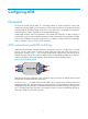
Configuring ATM Overview Asynchronous Transfer Mode (ATM) is a technology based on packet transmission mode while incorporating the high-speed of circuit transmission mode. ATM was adopted as the transmission and switching mode for broadband ISDN by the ITU-T in June 1992. Due to its flexibility and support for multimedia services, ATM is regarded as core broadband technology. As defined by the ITU-T, data is encapsulated in cells in ATM.
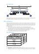
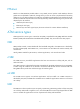
Figure 2 ATM switching ATM interfaces support only manually created permanent virtual circuits (PVCs), not switched virtual circuits (SVCs) created by exchanging signals and permanent virtual paths (PVPs). ATM architecture ATM has a three-dimensional architecture. It consists of three planes: user plane, control plane, and management plane.
them. Meanwhile, continuous bit streams received from physical media are restored to cells, which are then passed to the ATM layer. • ATM layer—Resides over the physical layer, and implements cell-based communication with its peer layer by invoking the services provided by the physical layer. It is independent of physical media, implementation of the physical layer, and types of services being carried.
PPPoEoA PPPoE over ATM (PPPoEoA) enables ATM to carry PPPoE protocol packets. With PPPoEoA, Ethernet packets are encapsulated in ATM cells, through which you can use a PVC to implement the functionality of Ethernet. To carry Ethernet frames over ATM, the virtual Ethernet (VE) interface was introduced. The VE interface has Ethernet characteristics and can be dynamically created.
InARP On an ATM PVC connection, you can use the Inverse Address Resolution Protocol (InARP) to obtain the IP address of the remote end connected to the PVC. In this way, you do not need to manually configure the IP address of the remote end. Figure 4 shows how InARP works. Figure 4 Inverse address resolution procedure of InARP ATM OAM OAM in the ITU-T I.610 recommendation (02/99) and Operation Administration and Maintenance in LUCENT APC User Manual (03/99).
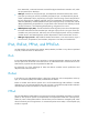
OAM CC works on a PVC, where one side of the PVC sends OAM cells to its peer. The peer checks the connection status based on these OAM cells. ATM configuration task list Task Remarks Configuring an ATM interface Required. Configuring an ATM subinterface Configuring PVCs and the maximum number of PVCs allowed on an interface Performing basic configurations for an ATM subinterface Checking PVC status to determine the protocol state of an ATM P2P subinterface Configuring PVC parameters Optional.
Step 1. Enter system view. Command Remarks system-view N/A By default, the connection type of a subinterface is point-to-multipoint (p2mp). 2. Create an ATM subinterface and enter its view. interface atm interface-number.subnumber [ p2mp | p2p ] 3. Set the MTU for the ATM subinterface. mtu mtu-number Shut down the ATM subinterface. shutdown 4. The keywords p2mp and p2p are available with the interface atm interface-number.subnumber command only when you are creating an ATM subinterface.
Configuring PVCs and the maximum number of PVCs allowed on an interface Configuring PVC parameters Step Command Remarks 1. Enter system view. system-view N/A 2. Enter ATM interface view or ATM subinterface view. interface atm { interface-number | interface-number.subnumber } N/A 3. Create a PVC and enter PVC view. pvc { pvc-name [ vpi/vci ] | vpi/vci } By default, no PVC is created. 4. Set the AAL5 encapsulation protocol type for the PVC. Optional.
Step Command Remarks • Set the PVC's service type to constant bit rate (CBR): service cbr output-pcr [ cdvt cdvt-value ] • Set the PVC's service type to 7. Set the PVC service type and the rate-related parameters. unspecified bit rate (UBR), and set the rate-related parameters: service ubr output-pcr • Set the PVC's service type to nrt-VBR, and set the rate-related parameters: service vbr-nrt output-pcr output-scr output-mbs • Set the PVC's service type to Optional.
Step Command Remarks 10. Return to system view. quit N/A 11. Enter ATM interface or subinterface view. interface atm { interface-number | interface-number.subnumber } N/A 12. Create a PVC and enter PVC view. pvc { pvc-name [ vpi/vci ] | vpi/vci } By default, no PVC is created. 13. Apply the QoS policy on the PVC. qos apply policy policy-name { inbound | outbound } N/A For more information about classes, traffic behaviors, and policies, see ACL and QoS Configuration Guide.
Step Command Remarks 2. Enter ATM interface or subinterface view. interface atm { interface-number | interface-number.subnumber } N/A 3. Create PVC, and enter its view. pvc { pvc-name [ vpi/vci ] | vpi/vci } N/A 4. Return to ATM interface or subinterface view. quit N/A 5. Create a PVC group and enter PVC group view. pvc-group { pvc-name [ vpi/vci ] | vpi/vci } Make sure that the PVC specified by the pvc-name or vpi/vci argument already exists. 6. Add a PVC to the PVC-Group.
class applied to the PVC, and the configuration performed to the ATM class applied to the ATM interface. • All the configurations directly performed to the PVC, performed to the ATM class applied to the PVC, and performed to the ATM class applied to the ATM interface take effect if they do not conflict.
Step Command Remarks • Configure IPoA and enable Optional. inverse address resolution (InARP) for the PVC: map ip inarp [ minutes ] [ broadcast ] 6. Configure the service type (use different commands according to service types). • Establish PPPoA mapping for • Establish IPoEoA or PPPoEoA Before configuring InARP, make sure the aal5snap encapsulation is used.
Table 1 Support for ATM applications ATM application aal5snap aal5mux aal5nlpid IPoA Supported Supported Supported IPoEoA Supported Supported Not supported PPPoA Supported Supported Not supported PPPoEoA Supported Supported Not supported High MBS settings might result in the failure of the service vbr-rt and vbr-nrt commands because of hardware limitations. To avoid the situation, set MBS to a smaller value. With aal5snap adopted, two or more protocols are supported.
Step Command Remarks N/A 1. Enter system view. system-view 2. Create a Layer 2 VE interface and enter the interface view. interface ve-bridge interface-number If a specified Layer 2 VE interface does not exist, use this command to first create one and then enter its view. You can create up to 1024 Layer 2 VE interfaces. Optional. 3. Set the interface description.
Step Command Configure an IPoA mapping for the PVC, and enable the PVC to carry IP packets. 4. map ip { ip-address [ ip-mask ] | default | inarp [ minutes ] } [ broadcast ] Remarks By default, no mapping is configured. If a mapping is configured, pseudo-broadcast is not supported by default. Before configuring InARP, make sure that aal5snap encapsulation is used. InARP is not supported when aal5mux or aal5nlpid encapsulations is adopted.
negotiation to accept the IP address allocated by the server end. For more information, see "Configuring PPP and MP." When you configure a static route for a virtual-template interface, specify the next hop rather than the outgoing interface. If you want to specify the outgoing interface, make sure the physical interface bound to the virtual-template is valid to ensure correct transmission. The following configurations enable the PVC to carry PPP and configure a PPP mapping for the PVC.
Step Command Remarks Enter system view. system-view N/A 2. Create a VT interface. interface virtual-template vt-number Configure PPP authentication and an IP address on the VT interface (the IP address is invalid if configured on the ATM interface). 3.
Task Command Remarks Display information about PVC mappings. display atm map-info [ interface interface-type interface-number [ pvc { pvc-name [ vpi/vci ] | vpi/vci } ] ] [ | { begin | exclude | include } regular-expression ] Available in any view. Display PVC-group information. display atm pvc-group [ interface interface-type interface-number [ pvc { pvc-name [ vpi/vci ] | vpi/vci } ] ] [ | { begin | exclude | include } regular-expression ] Available in any view.
Figure 5 Network diagram Configuration procedure 1. Configure Router A: # Enter the view of the ATM 1/0/1 interface and configure an IP address for it. system-view [RouterA] interface atm 1/0/1 [RouterA-Atm1/0/1] ip address 202.38.160.1 255.255.255.0 # Establish a PVC and enable it to carry IP. [RouterA-Atm1/0/1] pvc to_b 0/40 [RouterA-atm-pvc-Atm1/0/1-0/40-to_b] map ip 202.38.160.
[RouterC-atm-pvc-Atm1/0/1-0/60-to_a] map ip 202.38.160.1 [RouterC-atm-pvc-Atm1/0/1-0/60-to_a] quit [RouterC-Atm1/0/1] pvc to_b 0/61 [RouterC-atm-pvc-Atm1/0/1-0/61-to_b] map ip 202.38.160.2 IPoEoA configuration example Network requirements As shown in Figure 6, each of the hosts in the two Ethernets is respectively connected to the ATM network through an ADSL Router, and they communicate with Router C through DSLAM. The IP address of the VE interface of Router C is 202.38.160.1.
PPPoA configuration example Network requirements As shown in Figure 7, two hosts dial into the ATM network each through an ADSL Router, and communicate with Router C through DSLAM. The requirements are as follows: • To create VT for multiuser on Router C, and configure PPP mapping on VT. The VPI/VCI value of two PVCs connecting Router C and DSLAM are 0/60 and 0/61, pointing to ADSL Router A and ADSL Router B, respectively.
[RouterC-isp-system] quit # Create a VT interface, configure PAP authentication and an IP address, and allocate an IP address for the remote end from the IP address pool. [RouterC] interface virtual-template 10 [RouterC-Virtual-Template10] ip address 202.38.160.1 255.255.255.0 [RouterC-Virtual-Template10] ppp authentication-mode pap [RouterC-Virtual-Template10] remote address pool 1 [RouterC-Virtual-Template10] quit [RouterC] interface virtual-template 11 [RouterC-Virtual-Template11] ip address 202.38.161.
Figure 8 Network diagram Configuration procedure Configure Router C: # Configure the users in the domain to use the PPP authentication scheme, and create a local IP address pool.
[RouterC-Virtual-Ethernet2/0/1] pppoe-server bind virtual-template 11 [RouterC-Virtual-Ethernet2/0/1] quit # Establish a PVC and specify it to carry PPPoE. [RouterC] interface atm 1/0/1.1 [RouterC-Atm1/0/1.1] pvc to_adsl_a 0/60 [RouterC-atm-pvc-Atm1/0/1.1-0/60-to_adsl_a] map bridge virtual-ethernet 1/0/1 [RouterC-atm-pvc-Atm1/0/1.1-0/60-to_adsl_a] quit [RouterC-Atm1/0/1.1] pvc to_adsl_b 0/61 [RouterC-atm-pvc-Atm1/0/1.
After two equal traffic flows exceeding the ATM bandwidth are sent to Router B and Router C, you can use the display atm pvc-info interface atm 1/0/1 pvc command on Router B and Router C to view statistics for each PVC (you can make several tests and observe the average statistics). You can see that the PVC with higher priority receives more packets than that with lower priority.
interface are directly connected, they can communicate in most cases, but sometimes with frequent packet dropping and CRC errors. • If the two ends are PPPoA, make sure that their IP addresses (should be in the same network segment) and authentication parameters are correctly configured. • If, according to the ping command, small packets can pass but big packets cannot, make sure that the mtu configurations of the two router interfaces are the same.
Packet loss and CRC errors and changes of interface state Symptom Two routers are connected back-to-back, and a ping between them is successful, but sometimes there are large amount of packets lost and frequent CRC errors, or the interface state alternates between UP and DOWN. Solution Check the ATM interfaces of the two nodes to see if their types are the same (both are multimode fiber interface or both are single-mode fiber interface). If their types are different, you should change one of them.
Configuring PPP and MP Overview PPP Point-to-Point Protocol (PPP) is a link layer protocol carrying network layer packets over point-to-point links. It gains popularity because it provides user authentication, supports synchronous/asynchronous communication, and allows for easy extension. PPP contains a set of protocols, including: • Link control protocol (LCP)—Establishes, tears down, and monitors data links. • Network control protocol (NCP)—Negotiates the packet format and type for data links.
4. If a network layer protocol is configured, the PPP link enters the Network-Layer Protocol phase for NCP negotiation, such as IPCP negotiation or IPv6CP negotiation. If the NCP negotiation succeeds, the link goes up and becomes ready to carry negotiated network-layer protocol packets. If the NCP negotiation fails, NCP reports a down event and enters the Link Termination phase. 5. If the interface is configured with an IP address, the IPCP negotiation is performed.
{ MS-CHAP-V2 supports password changing. If the supplicant fails authentication because of an expired password, it will send the new password entered by the user to the authenticator for reauthentication. MP Multilink PPP (MP) enables you to bind multiple PPP links into one MP bundle for increasing bandwidth. After receiving a packet that is larger than the minimum packet size for fragmentation, MP fragments the packet and distributes the fragments across multiple PPP links to the peer end.
Step Command Remarks Optional. Enable PPP encapsulation on the interface. 3. link-protocol ppp By default, all interfaces except Ethernet interfaces and VLAN interfaces use PPP as the link layer protocol. Configuring PPP authentication You can configure several authentication modes simultaneously. In LCP negotiation, the authenticator negotiates with the supplicant in the sequence of configured authentication modes until the LCP negotiation succeeds.
Configuring CHAP authentication According to whether the authenticator is configured with a username or not, the configuration of CHAP authentication includes the following two types: 1. Configuring CHAP authentication when the authenticator name is configured To configure the authenticator: Step Command Remarks 1. Enter system view. system-view N/A 2. Enter interface view. interface interface-type interface-number N/A 3. Configure the local device to authenticate the supplicant by using CHAP.
Step Command Remarks For local AAA authentication, the username and password of the authenticator must be configured on the supplicant. For remote AAA authentication, the username and password of the authenticator must be configured on the remote AAA server. Configure local or remote AAA authentication. 4. The username configured for the authenticator must be the same as that configured on the authenticator. The passwords configured for the authenticator and supplicant must be the same.
Configuring MS-CHAP or MS-CHAP-V2 authentication When you configure MS-CHAP or MS-CHAP-V2 authentication, follow these guidelines: • In MS-CHAP or MS-CHAP-V2 authentication, an HP device can only be an authenticator • L2TP supports the MS-CHAP authentication but does not support the MS-CHAP-V2 authentication. • MS-CHAP-V2 authentication supports password changing only when using RADIUS.
Step Command Remarks For local AAA, the username and password of the supplicant must be configured on the authenticator. Configure local or remote AAA authentication. 4. For remote AAA authentication, the username and password of the supplicant must be configured on the remote AAA server. The username and password configured for the supplicant must be the same as those configured on the supplicant. For more information about AAA authentication, see Security Configuration Guide.
Step Command Remarks N/A 2. Enter interface view. interface interface-type interface-number 3. Configure the negotiation timeout time. ppp timer negotiate seconds Optional. 3 seconds by default.
To configure the local end as the server (for cases where PPP authentication is enabled): Step Command Remarks 1. Enter system view. system-view N/A 2. Enter ISP domain view. domain domain-name N/A 3. Define the domain address pool. ip pool pool-number low-ip-address [ high-ip-address ] You must define an address pool in a specified domain at the time of PPP authentication. 4. Return to system view. quit N/A 5. Enter interface view.
Step Command Enable the local end to accept the DNS server address assigned by the peer. 4. Remarks Optional. ppp ipcp dns admit-any By default, a device does not accept the DNS server address assigned by the peer. NOTE: The server will specify a DNS server address for a client in PPP negotiation only after the client is configured with the ppp ipcp dns request command.
Step Command Remarks 1. Enter system view. system-view N/A 2. Enter interface view. interface interface-type interface-number N/A 3. Restore the default settings for the interface. default For more information about restoring the default settings for an interface, see Interface Configuration Guide. Configuring MP The router only supports MP bundling across subcards on the same base card. However, an MP-group interface assigned a subcard number does not support cross-subcard MP bundling.
Task Remarks Configuring MP by using a VT interface Configuring MP through an MP-group interface Perform either task. Configuring short sequence number header format negotiation Optional. Configuring the MP endpoint descriptor Optional. Configuring MP by using a VT interface When you configure MP by using a VT interface, you can do one of the following: • Binding physical interfaces to the VT interface by using the ppp mp virtual-template command.
Step Command Remarks 6. Set the intended bandwidth for the VT interface. bandwidth bandwidth-value Optional. 7. Restore the default settings for the VT interface. default Optional. 8. Return to system view. quit N/A • (Method 1) Bind a physical interface to the VT interface: a. interface interface-type interface-number b. Specify the number of the VT interface to which the interface is to be bound, and specify that the interface operate in MP mode: ppp mp virtual-template number c. 9.
• After you configure the undo ppp mp fragment enable command on an interface, the settings configured with the ppp mp lfi and ppp mp min-fragment commands become invalid on the interface. • When MP binding is based on descriptor only, users cannot be differentiated. To bind users to different MP bundles, set the binding mode to both. • When MP binding is based on authentication username only, peer devices cannot be differentiated.
Configuring MP through an MP-group interface When you configure MP through an MP-group interface, follow these guidelines: • The ppp mp max-bind command and the ppp mp min-fragment command you configured can take effect on an MP bundle only after you re-enable all the physical interfaces in the MP bundle by executing the shutdown command and then the undo shutdown command.
• If the local end wants to receive fragments with short sequence numbers, it should request the peer to transmit short sequence numbers during LCP negotiation. After the negotiation succeeds, the peer transmits fragments with short sequence numbers. • If the local end wants to transmit fragments with short sequence numbers, it should ask the peer to send a request for receiving short sequence numbers during LCP negotiation.
CAUTION: Disabling LFI also removes the user-configured settings of maximum LFI fragment delay and size. On a low-speed serial link, packets of real-time interactive communications (such as Telnet and VoIP) might be blocked or delayed if packets of other applications are also transmitted across the link. For example, if a voice packet arrives when large packets are being scheduled and waiting to be transmitted, it must wait until all the large packets have been transmitted.
Step Command Remarks Use either command. 4. Set the maximum delay of transmitting an LFI fragment or the maximum size (in bytes) of LFI fragments. • ppp mp lfi delay-per-frag time • ppp mp lfi size-per-frag size The default maximum delay of transmitting an LFI fragment is 10 ms, and the default maximum size of LFI fragments depends on the configuration of the ppp mp lfi delay-per-frag command.
Figure 12 Network diagram Configuration procedure 1. Configure Router A: # Create a user account for Router B. system-view [RouterA] local-user userb # Set a password for the user account. [RouterA-luser-userb] password simple passb # Set the service type of the user account to PPP. [RouterA-luser-userb] service-type ppp [RouterA-luser-userb] quit # Enable PPP encapsulation on Serial 2/0/1.
The Maximum Transmit Unit is 1500, Hold timer is 10(sec) Internet Address is 200.1.1.2/16 Primary Link layer protocol is PPP LCP opened, IPCP opened Output queue : (Urgent queuing : Size/Length/Discards) 0/100/0 Output queue : (Protocol queuing : Size/Length/Discards) Output queue : (FIFO queuing : Size/Length/Discards) 0/500/0 0/75/0 Interface is V35 206 packets input, 2496 bytes 206 packets output, 2492 bytes [RouterB-Serial2/0/1] ping 200.1.1.1 PING 200.1.1.
[RouterA-Serial2/0/1] link-protocol ppp # Set the authentication mode to PAP. [RouterA-Serial2/0/1] ppp authentication-mode pap domain system # Configure the PAP username and password sent from Router A to Router B when Router A is authenticated by Router B using PAP. [RouterA-Serial2/0/1] ppp pap local-user usera password simple passa # Assign an IP address to Serial 2/0/1 of Router A. [RouterA-Serial2/0/1] ip address 200.1.1.
Internet Address is 200.1.1.2/16 Primary Link layer protocol is PPP LCP opened, IPCP opened Output queue : (Urgent queuing : Size/Length/Discards) 0/100/0 Output queue : (Protocol queuing : Size/Length/Discards) Output queue : (FIFO queuing : Size/Length/Discards) 0/500/0 0/75/0 Interface is V35 206 packets input, 2496 bytes 206 packets output, 2492 bytes [RouterB-isp-system] ping 200.1.1.1 PING 200.1.1.1: 56 data bytes, press CTRL_C to break Reply from 200.1.1.
[RouterA-Serial2/0/1] link-protocol ppp # Configure the username for Router A when Router A authenticates Router B. [RouterA-Serial2/0/1] ppp chap user usera # Set the authentication mode to CHAP. [RouterA-Serial2/0/1] ppp authentication-mode chap domain system # Assign an IP address to Serial 2/0/1. [RouterA-Serial2/0/1] ip address 200.1.1.1 16 [RouterA-Serial2/0/1] quit # Configure local authentication for the PPP users in the default ISP domain system.
[RouterA] domain system [RouterA-isp-system] authentication ppp local 4. Configure Router B: # Configure the username of Router B when Router B is authenticated. system-view [RouterB] interface serial 2/0/1 [RouterB-Serial2/0/1] ppp chap user userb # Set the default CHAP password. [RouterB-Serial2/0/1] ppp chap password simple hello # Assign an IP address to Serial 2/0/1. [RouterB-Serial2/0/1] ip address 200.1.1.2 16 5.
PPP IP address negotiation configuration example Network requirements As shown in Figure 15, configure Router A to allocate an IP address for Serial 2/0/1 of Router B through PPP negotiation. Figure 15 Network diagram Configuration procedure 1. Configure Router A: # Configure a local IP address pool. system-view [RouterA] ip pool 1 200.1.1.10 200.1.1.20 # Configure the IP address of Serial 2/0/1. [RouterA] interface serial 2/0/1 [RouterA-Serial2/0/1] ip address 200.1.1.
--- 200.1.1.1 ping statistics --5 packet(s) transmitted 5 packet(s) received 0.00% packet loss round-trip min/avg/max = 1/4/10 ms The output shows Serial 2/0/1 of Router A can be pinged. MP configuration example Network requirements As shown in Figure 16: • On an E1 interface of Router A, four channels are created with the interface names Serial 2/0/1:1, Serial 2/0/1:2, Serial 2/0/1:3, and Serial 2/0/1:4.
[RouterA] ppp mp user router-b bind virtual-template 1 [RouterA] ppp mp user router-c bind virtual-template 2 # Configure the VT interfaces. [RouterA] interface virtual-template 1 [RouterA-Virtual-Template1] ip address 202.38.166.1 255.255.255.0 [RouterA-Virtual-Template1] quit [RouterA] interface virtual-template 2 [RouterA-Virtual-Template2] ip address 202.38.168.1 255.255.255.
system-view [RouterC] local-user router-a [RouterC-luser-router-a] password simple router-a [RouterC-luser-router-a] service-type ppp [RouterC-luser-router-a] quit # Create a VT interface for the user and specify to use the NCP information of the interface for PPP negotiation. [RouterC] ppp mp user router-a bind virtual-template 1 # Configure the VT interface. [RouterC] interface virtual-template 1 [RouterC-Virtual-Template1] ip address 202.38.168.2 255.255.255.
# Configure Serial 2/0/2. [RouterA-Virtual-Template1] quit [RouterA] interface serial 2/0/2 [RouterA-Serial2/0/2] link-protocol ppp [RouterA-Serial2/0/2] ppp authentication-mode pap domain system [RouterA-Serial2/0/2] ppp pap local-user rta password simple rta [RouterA-Serial2/0/2] ppp mp virtual-template 1 [RouterA-Serial2/0/2] shutdown [RouterA-Serial2/0/2] undo shutdown [RouterA-Serial2/0/2] quit # Configure Serial 2/0/1.
[RouterB-Serial2/0/1] ppp authentication-mode pap domain system [RouterB-Serial2/0/1] ppp pap local-user rtb password simple rtb [RouterB-Serial2/0/1] ppp mp virtual-template 1 [RouterB-Serial2/0/1] shutdown [RouterB-Serial2/0/1] undo shutdown [RouterB-Serial2/0/1] quit # Configure local authentication for the PPP users in the default ISP domain system. [RouterB] domain system [RouterB-isp-system] authentication ppp local [RouterB-isp-system] quit 3.
5 packet(s) received 0.00% packet loss round-trip min/avg/max = 29/30/31 ms Because PPP authentication is configured on the physical interface, the bundle field in the output from the display ppp mp command is the peer username. If authentication is disabled, the bundle field should be the peer descriptor. In addition, you can check the state of MP virtual channels by checking the state of virtual access interfaces by using the display virtual-access command.
# Configure the username and password of Router A. system-view [RouterB] local-user rta [RouterB-luser-rta] password simple rta [RouterB-luser-rta] service-type ppp [RouterB-luser-rta] quit # Specify a VT interface to user RTA. [RouterB] ppp mp user rta bind virtual-template 1 # Create the VT interface and configure its IP address. [RouterB] interface virtual-template 1 [RouterB-Virtual-Template1] ip address 8.1.1.
Bundle rta, 2 member, Master link is Virtual-Template1:0 0 lost fragments, 0 reordered, 0 unassigned, 0 interleaved, sequence 0/0 rcvd/sent The bundled member channels are: Serial2/0/2 Serial2/0/1 # Display the status of the VA interfaces.
[RouterA-luser-rtb] quit # Create an MP-group interface, and assign an IP address to it. [RouterA] interface Mp-group 1 [RouterA-Mp-group1] ip address 111.1.1.1 24 # Configure Serial 2/0/2.
# Configure Serial 2/0/1. [RouterB] interface serial 2/0/1 [RouterB-Serial2/0/1] link-protocol ppp [RouterB-Serial2/0/1] ppp authentication-mode pap domain system [RouterB-Serial2/0/1] ppp pap local-user rtb password simple rtb [RouterB-Serial2/0/1] ppp mp Mp-group 1 [RouterB-Serial2/0/1] shutdown [RouterB-Serial2/0/1] undo shutdown [RouterB-Serial2/0/1] quit # Configure local authentication for the PPP users in the default ISP domain system.
5 packet(s) transmitted 5 packet(s) received 0.00% packet loss round-trip min/avg/max = 29/29/31 ms In this method, all the users are bound together to the MP-group interface and the concept of virtual access is not involved. Troubleshooting PPP configuration Symptom 1 PPP authentication always fails, preventing the link from going up. Solution This problem might occur if the parameters for authentication are incorrect.
Solution Do the following: • Enable IPv6 before configuring an IPv6 address on a PPP link. • If IPv6CP negotiation fails, re-enable the interface by executing the shutdown command and then the undo shutdown command to re-enable IPv6CP negotiation.
Configuring PPPoE Overview Point-to-Point Protocol over Ethernet (PPPoE) extends PPP by transporting PPP packets encapsulated in Ethernet over point-to-point links. PPPoE can provide access to the Internet for the hosts in an Ethernet through a remote access device and implement access control and accounting on a per-host basis. Integrating the low cost of Ethernet and scalability and management functions of PPP, PPPoE gained popularity in various application environments, such as residential networks.
Figure 19 Network structure 2 PPPoE client Host A PPPoE server Internet PPPoE client Router Host B Protocols and standards RFC 2516, A Method for Transmitting PPP Over Ethernet (PPPoE) Configuring a PPPoE server You can configure PPPoE servers on Ethernet ports or virtual Ethernet interfaces created on ADSL interfaces. For more information about configuring PPPoE servers on virtual Ethernet interfaces, see "Configuring ATM." Cross-card Layer 3 aggregate interfaces do not support this feature.
Step 8. 9. Command Remarks Set the maximum number of PPPoE sessions allowed for a local MAC address. pppoe-server max-sessions local-mac number Optional. Set the maximum number of PPPoE sessions allowed on a card. pppoe-server max-sessions slot slot-number total number 4096 by default. Optional. Optional. 10. Set the upper threshold for the PPPoE abnormal offline event count. pppoe-server abnormal-offline-count threshold number 65535 by default.
PPPoE server configuration example Network requirements As shown in Figure 20, Host A and Host B act as PPPoE clients and run PPPoE client dialup software. The Router acts as the PPPoE server, performing local authentication and assigning IP addresses to the users. The Router provides Internet access for Host A and Host B through Ethernet 1/1. It connects to the Internet through Serial 2/0/1. Figure 20 Network diagram Configuration procedure 1. Configure CHAP authentication: # Add a PPPoE user.
[Router-isp-system] ip pool 1 1.1.1.2 1.1.1.10 2. Configure MS-CHAP authentication: # Add a PPPoE user. system-view [Router] local-user user1 [Router-luser-user1] password simple pass1 [Router-luser-user1] service-type ppp [Router-luser-user1] quit # Configure virtual-template 1 on the Router. [Router] interface virtual-template 1 [Router-Virtual-Template1] ppp authentication-mode ms-chap domain system [Router-Virtual-Template1] remote address pool 1 [Router-Virtual-Template1] ip address 1.1.1.
Configuring L2TP Overview A VPDN is a VPN utilizing the dial-up function of public networks such as ISDN or PSTN networks to provide access services for enterprises, small ISPs, and telecommuters. VPDN provides an economical and effective point-to-point method for remote users to connect to their home LANs. VPDN technology uses a tunneling protocol to build secure VPNs for enterprises across public networks.
• LNS—An L2TP network server (LNS) functions as both the L2TP server and the PPP end system. It is usually an edge device on an enterprise network. An LNS is the other endpoint of an L2TP tunnel and is a peer to the LAC. It is the logical termination point of a PPP session tunneled by the LAC. The L2TP extends the termination point of a PPP session from a NAS to an LNS, logically.
• Session—A session corresponds to one PPP data stream between an LNS and a LAC and is multiplexed on a tunnel. A session can be set up only after the tunnel is created. Multiple L2TP tunnels can be established between an LNS and an LAC. Both control messages and PPP frames are transferred on the tunnel. L2TP uses hello packets to check a tunnel's connectivity. The LAC and the LNS regularly send hello packets to each other.
Figure 25 Client-initiated tunneling mode L2TP tunnel establishment process Figure 26 Typical L2TP network Figure 27 shows an L2TP call's setup procedure in NAS-initiated mode.
Figure 27 L2TP call setup procedure Remote system Host A LAC Router A LAC RADIUS server LNS Router B LNS RADIUS server (1) Call setup (2) PPP LCP setup (3) PAP or CHAP authenticaion (4) Access request (5) Access accept (6) Tunnel setup (7) CHAP authentication (challenge/response) (8) Authentication passes (9) User CHAP response, PPP negotiation parameter (10) Access request (11) Acesss accept (12) CHAP authentication twice (challenge/response) (13) Access request (14) Acesss accept (15) Authentication
15. The LNS assigns an internal IP address to the remote user. The user can now access the internal resources of the enterprise network. L2TP features • Flexible identity authentication mechanism and high security—L2TP by itself does not provide security for connections. However, it has all the security features of PPP and allows for PPP authentication (CHAP or PAP). L2TP can also cooperate with IPsec to guarantee data security, strengthening the resistance of tunneled data to attacks.
L2TP-based EAD is usually used for remote users. For LAN users, deploy portal authentication. • For information about packet-filter firewalls, AAA, RADIUS, and portal authentication, see Security Configuration Guide. Protocols and standards • RFC 1661, The Point-to-Point Protocol (PPP) • RFC 1918, Address Allocation for Private Internets • RFC 2661, Layer Two Tunneling Protocol "L2TP" L2TP configuration task list When configuring L2TP, perform the following operations: 1.
Task Remarks Specify the local name of the tunnel Configuring an LNS Creating a VT interface Required. Configuring the local address and the address pool for allocation Required. Configuring an LNS to grant certain L2TP tunneling requests Required. Configuring user authentication on an LNS Optional. Configuring AAA authentication for VPN users on an LNS Optional. Enabling L2TP for VPNs Optional. Configuring support of LNS for the IMSI or SN in PPP LCP negotiation Optional.
Step 4. Command Specify the local name of the tunnel. Remarks Optional. tunnel name name The system name of the device is used by default. Configuring an LAC An LAC is responsible for establishing tunnels with LNSs for users and sends user packets to LNSs through the tunnels. Before configuring an LAC, enable L2TP and create an L2TP group. Configuring an LAC to initiate tunneling requests for specified users An LAC initiates tunneling requests only to specified LNSs for specified users.
Configuring AAA authentication for VPN users on LAC side You can configure an LAC to perform AAA authentication for VPN users and initiate a tunneling request only for qualified users. No tunnel will be established for unqualified users. The device supports both local AAA authentication and remote AAA authentication: • For local AAA authentication, create a local user and configure a password for each remote user on the LAC.
Configuring an LNS An LNS responds to the tunneling requests from an LAC, authenticates users, and assigns IP addresses to users. Before configuring an LNS, enable L2TP and create an L2TP group. Creating a VT interface A VT interface is intended to provide parameters for virtual access interfaces to be dynamically created by the device, such as logical MP interfaces and logical L2TP interfaces. After an L2TP session is established, a virtual access interface is needed for a data exchange with the peer.
Step Command Specify the address pool for allocating an IP address to a PPP user, or assign an IP address to the user directly. 5. remote address { pool [ pool-number ] | ip-address } Remarks Optional. By default, address pool 0 (the default address pool) is used.
LCP renegotiation—The LNS ignores the LAC proxy authentication information and performs a new round of LCP negotiation with the user. • The three authentication methods have different priorities, where LCP renegotiation has the highest priority and proxy authentication has the lowest priority. Which method the LNS uses depends on your configuration: • If you configure both LCP renegotiation and mandatory CHAP authentication, the LNS uses LCP renegotiation.
Configuring AAA authentication for VPN users on an LNS Configure AAA on the LNS in the following cases: • Proxy authentication is configured on the LNS • Mandatory CHAP authentication is configured on the LNS • Mandatory LCP renegotiation authentication is configured on the LNS and the VT interface requires PPP user authentication. After you configure AAA on the LNS, the LNS can authenticate the identities (usernames and passwords) of VPN users for a second time.
Step Command Remarks 1. Enter system view. system-view N/A 2. Enter VT interface view. interface virtual-template virtual-template-number By default, no VT interface is created. 3. Initiate an IMSI or SN negotiation request. ppp lcp { imsi | sn } request By default, no IMSI or SN negotiation request is initiated. Optional. 4. 5. Configure a separator for splitting the peer username during negotiation.
To ensure tunnel security, enable tunnel authentication. To change the tunnel authentication key, do so after tearing down the tunnel. Otherwise, your change does not take effect. To configure L2TP tunnel authentication: Step Command Remarks 1. Enter system view. system-view N/A 2. Enter L2TP group view. l2tp-group group-number N/A 3. Enable L2TP tunnel authentication. tunnel authentication Configure the tunnel authentication key. tunnel password { simple | cipher } password 4. Optional.
Disconnecting tunnels by force Either the LAC or the LNS can initiate a tunnel disconnection request. You can also disconnect a tunnel when no users are online or a network failure occurs. Once a tunnel is disconnected, the control connection and all the sessions within the tunnel are removed. When a user dials in, a new tunnel is established. To disconnect tunnels by force: Task Command Remarks Disconnect tunnels by force. reset l2tp tunnel { id tunnel-id | name remote-name } Available in user view.
Figure 28 Network diagram Configuration procedure 1. Configure the LAC (NAS): # Configure IP addresses for interfaces. (Details not shown.) # Create a local user named vpdnuser, set the password, and enable the PPP service. system-view [LAC] local-user vpdnuser [LAC-luser-vpdnuser] password simple Hello [LAC-luser-vpdnuser] service-type ppp [LAC-luser-vpdnuser] quit # Configure interface Async 1/0/1. [LAC] interface async 1/0/1 [LAC-Async1/0/1] ip address 1.1.1.1 255.255.255.
[LNS] l2tp enable # Configure the VT interface. [LNS] interface virtual-template 1 [LNS-virtual-template1] ip address 192.168.0.1 255.255.255.0 [LNS-virtual-template1] ppp authentication-mode chap domain system [LNS-virtual-template1] remote address pool 1 [LNS-virtual-template1] quit # Create an L2TP group, specify the VT interface for receiving calls, and specify the name of the tunnel on the peer.
Figure 29 Network diagram Configuration procedure 1. Configure the LNS: # Configure IP addresses for the interfaces. (Details not shown.) # Configure the route between the LNS and the user host. (Details not shown.) # Create a local user named vpdnuser, set the password, and enable the PPP service. The username and password must match those configured on the client.
# Modify the connection attributes, setting the protocol to L2TP, the encryption attribute to customized and the authentication mode to CHAP. 3. Verify the configuration: # On the user host, initiate the L2TP connection. After the connection is established, the user host can obtain the IP address 192.168.0.2 and ping the private IP address of the LNS (192.168.0.1). # On the LNS, use the display l2tp session command to check the established L2TP session.
[LAC] local-user vpdn1 [LAC-luser-vpdn1] password simple 11111 [LAC-luser-vpdn1] service-type ppp [LAC-luser-vpdn1] quit [LAC] local-user vpdn2 [LAC-luser-vpdn2] password simple 22222 [LAC-luser-vpdn2] service-type ppp [LAC-luser-vpdn2] quit # Configure local authentication for the users. [LAC] domain aaa.net [LAC-isp-aaa.net] authentication ppp local [LAC-isp-aaa.net] quit [LAC] domain bbb.net [LAC-isp-bbb.net] authentication ppp local [LAC-isp-bbb.
[LAC-l2tp1] tunnel authentication [LAC-l2tp1] tunnel password simple 12345 2. Configure the LNS: # Enable L2TP. system-view [LNS] l2tp enable # Enable L2TP for VPNs. [LNS] l2tpmoreexam enable # Create two local users, set the passwords, and enable the PPP service.
[LNS-l2tp3] tunnel password simple 12345 [LNS-l2tp3] quit [LNS] l2tp-group 4 [LNS-l2tp4] tunnel name LNS [LNS-l2tp4] tunnel authentication [LNS-l2tp4] allow l2tp virtual-template 2 remote LAC-1 domain bbb.net [LNS-l2tp4] tunnel password simple 12345 If RADIUS authentication is required on the LNS, modify the AAA configurations as needed. For AAA configuration details, see Security Configuration Guide. 3. Configure the users: Create a dial-up connection on each host: On Host A, enter vpdn1@aaa.
Troubleshooting L2TP The VPN connection setup process is complex. The following presents an analysis of some common faults that may occur in the process. Before troubleshooting the VPN, make sure that the LAC and LNS are connected properly across the public network. Symptom 1 Users cannot log in. Analysis and solution Possible reasons for login failure include: • Tunnel setup failure, which may occur in the following cases: { { { { • The address of the LNS is set incorrectly on the LAC.
Configuring HDLC High-level Data Link Control (HDLC) is a bit-oriented link layer protocol. Its most prominent feature is that it can transmit any type of bit stream transparently. • HDLC supports point-to-point link only and does not support point-to-multipoint link. • HDLC supports neither IP address negotiation nor authentication. It uses keepalive messages to check link status. • HDLC works only on synchronous interfaces or synchronous/asynchronous interfaces in synchronous mode.
Step Command Remarks PPP is encapsulated by default. Enable HDLC encapsulation on the interface. 3. You can use the display interface command to display the configuration and the reset counters interface command to clear interface statistics and restart statistics collection. link-protocol hdlc Configuring an IP address for an interface Make sure that an IP unnumbered HDLC interface has a route to the remote end.
Step Restore the default settings for the interface. 3. Command Remarks default For more information about restoring the default settings for an interface, see Interface Configuration Guide. Configuring the link status polling interval HDLC can regularly check link status. The link status polling interval is user configurable. It is a good practice to set the same interval for the two ends of a link. Setting the link status polling interval to 0 disables link status check.
system-view [RouterB] interface pos 1/0/1 [RouterB-Pos1/0/1] link-protocol hdlc [RouterB-Pos1/0/1] ip address 12.1.1.2 24 After the configuration, Router A and Router B should be able to ping each other. Take the output on Router A as an example. [RouterA] ping 12.1.1.2 PING 12.1.1.2: 56 data bytes, press CTRL_C to break Reply from 12.1.1.2: bytes=56 Sequence=1 ttl=255 time=126 ms Reply from 12.1.1.2: bytes=56 Sequence=2 ttl=255 time=1 ms Reply from 12.1.1.
[RouterA-Pos1/0/1] quit 2. Configure Router B: system-view [RouterB] interface pos 1/0/1 [RouterB-Pos1/0/1] link-protocol hdlc [RouterB-Pos1/0/1] ip address 12.1.1.1 24 3. Configure a static route on Router A: [RouterA] ip route-static 12.1.1.0 24 pos 1/0/1 [RouterA] ip route-static 12.1.2.0 24 12.1.1.1 4. Verify that Router A can ping network segment 12.1.2.0/24: [RouterA] ping 12.1.2.1 PING 12.1.2.1: 56 data bytes, press CTRL_C to break Reply from 12.1.2.
Configuring HDLC link bundling Overview HDLC link bundling allows you to bundle multiple interfaces using HDLC encapsulation together to form one logical link. HDLC link bundling delivers the following benefits: • Load balancing—Incoming/outgoing traffic is distributed across multiple member interfaces of the HDLC link bundle. • Increased bandwidth—The bandwidth on the HDLC link bundle interface is the total bandwidth of all available member interfaces.
• Ready—The member interface is up at the link layer and meets the conditions for being a selected interface, but is not selected yet due to the limitation on the maximum number of selected member interfaces, the minimum number of selected member interfaces required for bringing up the HDLC link bundle, or the minimum amount of bandwidth required for bringing up the HDLC link bundle.
If an HDLC link bundle does not contain any selected member interfaces, the HDLC link bundle interface is brought down, and cannot forward traffic. It will not be brought up and forward traffic until selected member interfaces are detected in the HDLC link bundle. The bandwidth of an HDLC link bundle is the total bandwidth of all selected member interfaces. Load balancing modes An HDLC link bundle forwards traffic through its selected member interfaces.
Step Command Remarks Optional. By default: • If all member interfaces of the HDLC link bundle interface are on the same card, the card processes or forwards traffic for the bundle interface. • If the member interfaces 4. Specify a card to forward traffic for the HDLC link bundle interface. service slot slot-number are on different cards, the card with the first selected member interface on the member list processes or forwards traffic for the bundle interface.
Step Command Remarks Optional. 1500 bytes by default. 9. Specify the MTU size on the HDLC link bundle interface. mtu size The MTU size specified here affects the fragmentation and reassembly of IP packets. Use this command to set a proper MTU size according to your network conditions. Make sure the largest MTU supported by the member interface is no less than the MTU size configured for the HDLC link bundle interface. Otherwise, traffic might fail to be forwarded. 10.
• The peer interface directly connected to an HDLC link bundle member interface must also join the HDLC link bundle. • The bundle member-priority command and the bundle max-active links command usually need to be used in conjunction, so that interconnected interfaces on two different devices can be both selected at the same time and exchange traffic successfully. To assign an interface to an HDLC link bundle: Step Command Remarks 1. Enter system view. system-view N/A 2.
Figure 33 Network diagram Configuration procedure 1. Configure Router A: # Create HDLC link bundle interface 1 and assign an IP address for it. system-view [RouterA] interface hdlc-bundle 1 [RouterA-Hdlc-bundle1] ip address 1.1.1.1 24 [RouterA-Hdlc-bundle1] quit # Assign POS interfaces POS 1/0/1 and POS 1/0/2 (both use the master clock mode) to HDLC link bundle 1.
Take the output on Router A for example. [RouterA] display interface hdlc-bundle 1 Hdlc-bundle1 current state: UP Line protocol current state: UP Description: Hdlc-bundle1 Interface The Maximum Transmit Unit is 1500 Internet Address is 1.1.1.
Configuring frame relay Overview Frame relay is essentially simplified X.25 WAN technology. It uses statistical multiplexing technology and can establish multiple virtual circuits over a single physical cable to make full use of network bandwidth. Frame relay uses data link connection identifiers (DLCIs) to identify virtual circuits and maintain the status of each virtual circuit with the Local Management Interface (LMI) protocol.
Virtual circuit Virtual circuits are logical paths established between two devices. Depending on how they are set up, virtual circuits include the following types: • Permanent virtual circuits (PVCs)—Preconfigured by network administrators and maintain until being manually removed. • Switched virtual circuits (SVCs)—Analogous to dialup connections. They are dynamically set up or cleared on an as-needed basis through protocol negotiation. PVCs are used far more than SVCs.
LMI protocol Frame relay uses the LMI protocol to set up virtual circuits and maintain their status between DTE and DCE. The system supports the following LMI standards: • ITU-T Q.933 Annex A • ANSI T1.617 Annex D • Nonstandard LMI (compatible with other vendors) To communicate correctly, the DTE and the DCE must use the same type of LMI.
Device role Timer/counter Keepalive (polling verification) timer (T392) Value range 5 to 30 Default value Description 15 Sets the interval (in seconds) for receiving a status inquiry message. If no status inquiry message is received before the timer expires, an error is recorded. Typical application scenarios As shown in Figure 35, you can use frame relay to construct a public or private network, and even direct connections between data equipment, as shown in Figure 36.
Task Remarks Enabling the trap function Optional You can configure an NNI interface in the same way a DCE interface is configured. For the configuration procedure, see "Configuring DCE side frame relay." If one endpoint of a link is an NNI interface, the peer endpoint must also be an NNI interface. Configuring DTE side frame relay Configuring basic DTE side frame relay Step Command Remarks 1. Enter system view. system-view N/A 2.
Configuration guidelines • Do not configure DLCIs for PVCs if static address mappings are configured. • Do not configure static address mapping on a P2P subinterface. A P2P subinterface carries only one PVC. Configuring static frame relay address mappings Step Command Remarks 1. Enter system view. system-view N/A 2. Enter interface view. interface interface-type interface-number N/A 3. Create a static frame relay address mapping.
Step Configure a virtual circuit on the interface. 3. Command Remarks fr dlci dlci-number By default, no virtual circuits are created on interfaces. Configuring a frame relay subinterface Frame relay offers two types of interfaces: main interface and subinterface. The subinterface is of logical structure, which can be configured with protocol address and virtual circuit. One physical interface can include multiple subinterfaces, which do not exist physically.
Configuring DCE side frame relay Configuring basic DCE side frame relay Step Command Remarks 1. Enter system view. system-view N/A 2. Enter interface view. interface interface-type interface-number N/A 3. Enable frame relay on the interface. link-protocol fr [ ietf | nonstandard ] The default link layer protocol on a WAN interface is PPP. If frame relay is enabled with no operating mode specified, the IETF standard applies. 4. Configure the frame relay interface type as DCE or NNI.
The interfaces used for frame relay switching must be NNI or DCE. To configure frame relay switching: Step Command Remarks 1. Enter system view. system-view N/A 2. Enable frame relay switching. fr switching N/A 3. Enter interface view. interface interface-type interface-number N/A 4. Set the type of an interface for frame relay switching to NNI or DCE. fr interface-type { dce | nni } The default frame relay interface type is DTE, which does not support frame relay switching.
Task Display frame relay protocol status on an interface. Command Remarks display interface mfr { interface-number | interface-number.subnumber } [ brief ] [ | { begin | exclude | include } regular-expression ] Available in any view. display interface [ mfr ] [ brief [ down ] ] [ | { begin | exclude | include } regular-expression ] Display the mapping table of protocol address and frame relay address. display fr map-info [ interface interface-type { interface-number | interface-number.
Figure 37 Network diagram Router A Router B S2/0/1 202.38.163.251/24 S2/0/1 202.38.163.252/24 DLCI=50 DLCI=70 Router C DLCI=60 FR S2/0/1 202.38.163.253/24 DLCI=80 Configuration procedure 1. Configure Router A: # Assign an IP address to interface Serial 2/0/1. system-view [RouterA] interface serial 2/0/1 [RouterA-Serial2/0/1] ip address 202.38.163.251 255.255.255.0 # Enable frame relay on the interface.
[RouterC-Serial2/0/1] fr interface-type dte # If the opposite router supports InARP, configure dynamic address mapping. [RouterC-Serial2/0/1] fr inarp # Otherwise, configure a static address mapping. [RouterC-Serial2/0/1] fr map ip 202.38.163.251 80 Connecting LANs with a dedicated line Network requirements As shown in Figure 38, two routers are directly connected with serial interfaces. Router A operates in DCE mode, and Router B operates in DTE mode.
[RouterA-Serial2/0/1] quit # Configure the IP address and DLCI of the subinterface Serial 2/0/1.1. [RouterA] interface serial 2/0/1.1 p2p [RouterA-Serial2/0/1.1] ip address 202.38.163.251 255.255.255.0 [RouterA-Serial2/0/1.1] fr dlci 100 4. Configure Router B: # Enable frame relay on interface Serial 2/0/1 and configure the interface to operate in DTE mode.
Configuring multilink frame relay Overview Multilink frame relay (MFR) is a cost effective bandwidth solution. It is based on the FRF.16 protocol of the frame relay forum and implemented on DTE/DCE interfaces. MFR provides MFR interfaces, a type of logical interface. An MFR interface is formed by a bundle of frame relay physical links to provide high transmission speed and bandwidth beyond the capabilities of a single link.
Step Command Remarks Optional. 3. Set the MFR bundle identifier. mfr bundle-name [ name ] The default bundle identifier is MFR + frame relay bundle number, for example, MFR4. You cannot set a bundle identifier in the MFR number format. Optional. 4. Enable MFR fragmentation. 5. Configure the size of the MFR sliding window. mfr window-size number 6. Configure maximum fragment size for bundle link. mfr fragment-size bytes mfr fragment By default, MRF fragmentation is disabled. Optional.
Step Command Optional. 4. Configure the MFR bundle link identifier. mfr link-name [ name ] 5. Configure the hello message sending interval for the MFR bundle link. mfr timer hello seconds Configure the waiting time before the MFR bundle link resends hello messages. mfr timer ack seconds Configure the maximum times that the MFR bundle link can resend hello messages. mfr retry number 6. 7. Remarks By default, the name of the current interface is used. Optional.
# Create and configure MFR interface 4 (MFR4). system-view [RouterA] interface mfr 4 [RouterA-MFR4] ip address 10.140.10.1 255.255.255.0 [RouterA-MFR4] fr interface-type dte [RouterA-MFR4] fr map ip 10.140.10.2 100 [RouterA-MFR4] quit # Bundle Serial 2/0/1 and Serial 2/0/2 to MFR4. [RouterA] interface serial 2/0/1 [RouterA-Serial2/0/1] link-protocol fr mfr 4 [RouterA-Serial2/0/1] quit [RouterA] interface serial 2/0/2 [RouterA-Serial2/0/2] link-protocol fr mfr 4 2.
[RouterA] interface mfr 1 [RouterA-MFR1] ip address 1.1.1.1 255.0.0.0 [RouterA-MFR1] quit # Add Serial 2/0/1 and Serial 2/0/2 to interface MFR1. [RouterA] interface serial 2/0/1 [RouterA-Serial2/0/1] link-protocol fr mfr 1 [RouterA-Serial2/0/1] quit [RouterA] interface serial 2/0/2 [RouterA-Serial2/0/2] link-protocol fr mfr 1 [RouterA-Serial2/0/2] quit 2. Configure Router B: # Enable frame relay switching. system-view [RouterB] fr switching # Configure interface MFR1.
[RouterC-MFR2] ip address 1.1.1.2 255.0.0.0 [RouterC-MFR2] quit # Add Serial 2/0/1 and Serial 2/0/2 to interface MFR2.
Managing a modem This chapter describes how to manage and control the modem connected to the device. Setting the modem answer mode To ensure correct modem operations, you must set the modem answer mode to be the same as the answer mode of the modem: • If the modem is in auto-answer mode (a modem is in auto-answer mode if its AA LED is on), use the modem auto-answer command to prevent the device from issuing answer instructions.
Solution • Use the shutdown command and undo shutdown command on the device physical interface connected to the modem to check whether the modem has been restored to normal status. • If the modem is still in abnormal status, repower the modem.
Support and other resources Contacting HP For worldwide technical support information, see the HP support website: http://www.hp.
Conventions This section describes the conventions used in this documentation set. Command conventions Convention Description Boldface Bold text represents commands and keywords that you enter literally as shown. Italic Italic text represents arguments that you replace with actual values. [] Square brackets enclose syntax choices (keywords or arguments) that are optional. { x | y | ... } Braces enclose a set of required syntax choices separated by vertical bars, from which you select one.
Network topology icons Represents a generic network device, such as a router, switch, or firewall. Represents a routing-capable device, such as a router or Layer 3 switch. Represents a generic switch, such as a Layer 2 or Layer 3 switch, or a router that supports Layer 2 forwarding and other Layer 2 features. Represents an access controller, a unified wired-WLAN module, or the switching engine on a unified wired-WLAN switch. Represents an access point.
Index ACDEFHILMOPRST Displaying and maintaining PPP and MP,47 A Displaying and maintaining PPPoE,69 Assigning an interface to an HDLC link bundle,106 ATM configuration examples,19 E ATM configuration task list,6 Enabling HDLC encapsulation on an interface,97 ATM OAM,5 Enabling the trap function,118 ATM service types,4 F C Frame relay configuration examples,119 Configuring a PPPoE server,68 Frame relay configuration task list,113 Configuring an ATM class,11 H Configuring an ATM interface,6
Troubleshooting,129 Restoring the default settings for an interface,98 Troubleshooting ATM,26 S Troubleshooting frame relay,122 Setting the modem answer mode,129 Troubleshooting L2TP,96 T Troubleshooting PPP configuration,65 135