HP 6600/HSR6600 Routers OAA Configuration Guide Part number: 5998-1513 Software version: A6602-CMW520-R3103 A6600-CMW520-R3102-RPE A6600-CMW520-R3102-RSE HSR6602_MCP-CMW520-R3102 Document version: 6PW103-20130628
Legal and notice information © Copyright 2013 Hewlett-Packard Development Company, L.P. No part of this documentation may be reproduced or transmitted in any form or by any means without prior written consent of Hewlett-Packard Development Company, L.P. The information contained herein is subject to change without notice.
Contents Configuring OAP modules ·········································································································································· 1 Logging in to the operating system of an OAP module ································································································ 1 Logging in through the console port on the OAP module ···················································································· 1 Logging in through the management Ethernet por
Configuring OAP modules The HP Open Application Architecture (OAA) provides an open interface for third-party vendors to develop value-added applications (such as firewall and IPS) and integrate the applications into HP products. HP has developed some application-specific modules called "Open Application Platform (OAP) module." The following matrix shows the OAP feature and router compatibility: 6602 HSR6602 6604/6608/6616 No. No. Yes when RPE-X1 and RSE-X1 MPUs are used and no when MCP MPUs are used.
1. Log in to the OAP module through the console port, and then enable the SSH server function on the OAP module. 2. Connect the management Ethernet port of the OAP module to the network by using a network cable. 3. Assign an IP address to the management Ethernet port of the OAP module, and make sure the SSH client (the HP device or a PC that has the SSH client software installed) and the management Ethernet port can reach each other. 4.
Resetting OAP modules CAUTION: To avoid data loss, shut down (poweroff) the operating system of the OAP module before you reset an OAP module. To recover an OAP module from an error condition, reboot the module at the CLI or press the reset button on the module. The device can still identify and control the OAP module after the reset. To reset the OAP module, execute the following command in user view: Task Command Reset the OAP module.
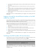
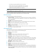
Configuring ACFP The following matrix shows the ACFP feature and router compatibility: 6602 HSR6602 6604/6608/6616 No. No. Yes when RPE-X1 and RSE-X1 MPUs are used and no when MCP MPUs are used. Overview The Application Control Forwarding Protocol (ACFP) is designed based on the OAA architecture and operates in the server/client model (see Figure 1).
• Mirroring and redirecting the traffic on the ACFP server to the ACFP client. • Permitting/denying the traffic from the ACFP server. • Restricting the rate of the traffic on the ACFP server. • Carrying the context ID in a packet to enable the ACFP server and ACFP client to communicate the packet context with each other. The ACFP server maintains a context table that can be queried by context ID.
{ HG-context (carrying the preamble HG as the context ID) { HGPlus-context (carrying the preamble HGPlus as the context ID) { FlowID-context (carrying the preamble Flow ID as the context ID) { VLANID-context (carrying VLAN ID as the context ID) NOTE: 6600 and HSR6600 routers support only VLANID-context. ACFP server information indicates the collaboration capabilities of an ACFP server. ACFP clients can access this information through a collaboration protocol or collaboration MIB.
• Priority—Priority of the policy, a number in the range of 1 to 8. The bigger the number, the higher the priority. ACFP collaboration rules ACFP collaboration rules refer to the collaboration rules that the ACFP client sends to the ACFP server for application. Collaboration rules include the following categories: • Monitoring rules—Used to monitor, analyze, and process packets to be sent to the ACFP client. Rule actions include redirect and mirror.
• Pro—Protocol type: GRE, ICMP, IGMP, OSPF, TCP, UDP, or IP. • IP precedence—Packet precedence, a number in the range of 0 to 7. • IP ToS—ToS of IP. • IP DSCP—DSCP of IP. • TCP flag—Some bits in the six flag bits (URG, ACK, PSH, RST, SYN, and FIN) are concerned. • IP fragment—Whether the packet is an IP packet fragment. • Rate limit. You can use the collaboration policy to manage the collaboration rules that belong to it.
ACFP configuration task list Task Remarks Enabling the ACFP server on the device Required. Configuring the ACFP client (the OAP module) Required. Enabling the ACFP trap function on the device Optional. Enabling the ACFP server on the device Step Command Remarks 1. Enter system view. system-view N/A 2. Enable the ACFP server. acfp server enable Disabled by default.
Trap message Level ACFP collaboration rules failed Errors Expiration period of ACFP collaboration policy timed out Notifications The generated trap messages are sent to the information center of the device. With the parameters for the information center set, the output rules for traps (that is, whether the traps are allowed to be output and the output destinations) are decided.
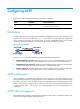
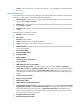
Configure the ACFP client to analyze traffic arriving at interface GigabitEthernet 3/0/2, and control the traffic as follows: • Permit all packets whose source IP address is 192.168.1.1/24. • Deny all packets whose source IP address is 192.168.1.2/24. Figure 2 Network diagram ACFP client GE3/0/3 GE3/0/2 Router GE3/0/1 ACFP server Host A Host B Host C Host D 192.168.1.1/24 192.168.1.2/24 192.168.2.1/24 192.168.2.2/24 Configuration procedure 1.
action. Set the value of the node hh3cAcfpRuleSrcIP to 192.168.1.1 and set the value of the node hh3cAcfpRuleSrcIPMask to 0.0.0.255 to match packets from 192.168.1.1/24. c. Set the value of the node hh3cAcfpRuleRowStatus to 4 to create an ACFP rule, and assign index 1.2.2 to the rule. Set the value of the node hh3cAcfpRuleAction to 2 to specify the deny action. Set the value of the node hh3cAcfpRuleSrcIP to 192.168.1.2 and set the value of the node hh3cAcfpRuleSrcIPMask to 0.0.0.
Configuring ACSEI The following matrix shows the ACSEI feature and router compatibility: 6602 HSR6602 6604/6608/6616 No. No. Yes when RPE-X1 and RSE-X1 MPUs are used and no when MCP MPUs are used. Overview HP ACFP Client and Server Exchange Information (ACSEI) provides a method for exchanging information between an ACFP server and its ACFP clients. As a supporting protocol for ACFP collaboration, ACSEI makes sure an ACFP server can cooperate with its ACFP clients to provide services.
• Clock synchronization timer—Used to periodically trigger the ACSEI server to send clock synchronization advertisements to the ACSEI clients. • Client monitoring timer—Used to periodically trigger the ACSEI server to send monitoring requests to the ACSEI clients. An ACSEI client also uses two timers, neither of which are configurable: • Registration timer—Used to periodically trigger the ACSEI client to multicast registration requests (with the multicast MAC address 010F-E200-0021).
Displaying ACSEI client information on the server side Task Command Remarks Display ACSEI client summary. display acsei client summary [ client-id ] [ | { begin | exclude | include } regular-expression ] Available in any view. Display ACSEI client information. display acsei client info [ client-id ] [ | { begin | exclude | include } regular-expression ] Available in any view.
Support and other resources Contacting HP For worldwide technical support information, see the HP support website: http://www.hp.
Conventions This section describes the conventions used in this documentation set. Command conventions Convention Description Boldface Bold text represents commands and keywords that you enter literally as shown. Italic Italic text represents arguments that you replace with actual values. [] Square brackets enclose syntax choices (keywords or arguments) that are optional. { x | y | ... } Braces enclose a set of required syntax choices separated by vertical bars, from which you select one.
Network topology icons Represents a generic network device, such as a router, switch, or firewall. Represents a routing-capable device, such as a router or Layer 3 switch. Represents a generic switch, such as a Layer 2 or Layer 3 switch, or a router that supports Layer 2 forwarding and other Layer 2 features. Represents an access controller, a unified wired-WLAN module, or the switching engine on a unified wired-WLAN switch. Represents an access point.
Index ACDELOR Enabling the ACFP server on the device,9 A Enabling the ACFP trap function on the device,9 ACFP configuration example,10 ACFP configuration task list,9 L C Logging in to the operating system of an OAP module,1 Configuring the ACFP client (the OAP module),9 O Configuring the ACSEI server,14 Contacting HP,16 Overview,13 Conventions,17 Overview,4 D R Displaying ACSEI client information on the server side,15 Related information,16 Resetting OAP modules,3 Displaying and maintaining