
R3102-R3103-HP 6600/HSR6600 Routers High Availability Configuration Guide

233
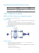
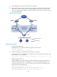
The default gateway of the hosts in the LAN is 192.168.0.10.
When Router A works correctly, hosts in the LAN access the external network through Router A.
When Router A detects that the uplink is down through BFD, it decreases its priority so that
Router B can preempt as the master, ensuring that the hosts in the LAN can access the external
network through Router B.
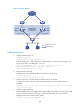
Figure 62 Network diagram
Configuration procedure
1. Configure BFD on Router A:
# Configure the source address of BFD echo packets as 10.10.10.10.
<RouterA> system-view
[RouterA] bfd echo-source-ip 10.10.10.10
2. Create the track entry to associate with the BFD session on Router A:
# Create track entry 1 for the BFD session on Router A to check whether the uplink device with
the IP address 1.1.1.2 is reachable.
[RouterA] track 1 bfd echo interface gigabitethernet 1/0/1 remote ip 1.1.1.2 local
ip 1.1.1.1
3. Configure VRRP on Router A:
# Create VRRP group 1, and configure the virtual IP address of the group as 192.168.0.10.
Configure the priority of Router A in VRRP group 1 as 110, and configure VRRP group 1 to
monitor the status of track entry 1. When the status of the track entry becomes Negative, the
priority of Router A decreases by 20.
[RouterA] interface gigabitethernet 1/0/2
[RouterA-GigabitEthernet1/0/2] vrrp vrid 1 virtual-ip 192.168.0.10
[RouterA-GigabitEthernet1/0/2] vrrp vrid 1 priority 110
[RouterA-GigabitEthernet1/0/2] vrrp vrid 1 track 1 reduced 20
Internet
Master
uplink device
Backup
uplink device
Uplink
Virtual Router
Virtual IP address:
192.168.0.10
GE1/0/2
192.168.0.101/24
GE1/0/2
192.168.0.102/24
Router A
Master
Router B
Backup
GE1/0/1
1.1.1.1/24
GE1/0/1
1.1.1.2/24
L2 switch
Uplink
VRRP packets
BFD probe packets