
R3102-R3103-HP 6600/HSR6600 Routers High Availability Configuration Guide


61
Step
Command
Remarks
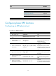
8. Set the actions that the
interface performs for an
alarm.
alarm-detect { rdi | sd | sf } action
link-down
Optional.
By default, the interface does not
perform any action for an alarm.
Support for the command
depends on the device model.
9. Set the maximum available
bandwidth for the interface.
bandwidth bandwidth-value
Optional.
10. Shut down the interface.
shutdown
Optional.
Enabled by default.
11. Restore the default settings
of the interface.
default
Optional.
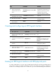
Creating and configuring an RPR logical interface
Step
Command
Remarks
1. Enter system view.
system-view
N/A
2. Create an 3 RPR logical
interface and enter RPR logical
interface view.
interface rpr interface-number
N/A
3. Configure the description for the
interface.
description text
Optional.
By default, the description of an
RPR interface is interface-name
Interface.
4. Configure the MTU of the
interface.
mtu size
Optional.
1500 bytes by default.
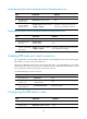
5. Specify the card for forwarding
traffic of the interface.
service slot slot-number
Optional.
By default, the card where the
receiving member port resides
processes the traffic.
6. Set the maximum available
bandwidth for the interface.
bandwidth bandwidth-value
Optional.
7. Shut down the interface.
shutdown
Optional.
Enabled by default.
8. Restore the default settings for
the interface.
default
Optional.
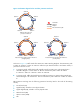
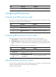
Binding an RPR logical interface with RPR physical ports
To create an RPR station, you must create an RPR logical interface first and then bind RPR physical
ports with the interface. You might bind RPR physical ports with an RPR logical interface in RPR logical
interface view or RPR physical port view. In either case, you must create the RPR logical interface first.