
R3102-R3103-HP 6600/HSR6600 Routers High Availability Configuration Guide

71
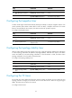
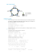
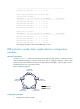
Figure 15 Network diagram
Configuration procedure
1. Create an RPR logical interface and bind two RPR physical ports to the RPR logical interface:
# On Station A, create RPR logical interface RPR1, and bind RPR physical ports RPRPOS 1/1
(the west port) and RPRPOS 1/2 (the east port) to RPR 1.
<StationA> system-view
[StationA] interface rpr 1
[StationA-RPR1] rpr bind rprpos 1/1 ringlet0
[StationA-RPR1] rpr bind rprpos 1/2 ringlet1
[StationA-RPR1] quit
Configure Station B, C, D, and E in the same way Station A is configured. (Details not shown.)
2. Verify the configuration:
# Display RPR interface binding information on Station A.
[StationA] display rpr bind-info
Bind information on interface: RPR1
PHY-Interface Ringlet-ID Role Mate-Port
---------------------------------------------------
RPRPOS1/1 Ringlet0 Master Up
RPRPOS1/2 Ringlet1 Slave Up
# Display the RPR topology summary on Station A.
[StationA] display rpr topology all summary
Topology information items
Psw:protection state, west Pse:protection state, east
Esw:edge state, west Ese:edge state, east
Wc:wrap protection configured Jp:jumbo frame preferred
Ring-level topology information on interface: RPR1
Ringlet0 Ringlet1 Ring Jumbo-Prefer Topology-Type
-------------------------------------------------
4 4 5 Regular Closed ring
Local station topology information on interface: RPR1
MAC-Address Psw Pse Esw Ese Wc Jp IP-Address Station-Name
Station E
000F-E257-0005
Station D
000F-E257-0004
Station C
000F-E257-0003
Station B
000F-E257-0002
Station A
000F-E257-0001
Ringlet 1
Ringlet 0
East port (RPRPOS1/2)
West port (RPRPOS1/1)