
R3102-R3103-HP 6600/HSR6600 Routers Layer 3 - IP Routing Configuration Guide

118
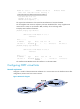
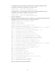
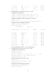
Destinations : 10 Routes : 10
Destination/Mask Proto Pre Cost NextHop Interface
3.1.1.0/24 O_ASE 150 1 10.2.1.2 GE2/1/2
3.1.2.0/24 O_ASE 150 1 10.2.1.2 GE2/1/2
10.1.1.0/24 Direct 0 0 10.1.1.1 GE2/1/1
10.1.1.1/32 Direct 0 0 127.0.0.1 InLoop0
10.2.1.0/24 Direct 0 0 10.2.1.1 GE2/1/2
10.2.1.1/32 Direct 0 0 127.0.0.1 InLoop0
10.3.1.0/24 OSPF 10 4 10.1.1.2 GE2/1/1
10.4.1.0/24 OSPF 10 13 10.2.1.2 GE2/1/2
127.0.0.0/8 Direct 0 0 127.0.0.1 InLoop0
127.0.0.1/32 Direct 0 0 127.0.0.1 InLoop0
The route to 10.5.1.1/24 is filtered out.
Configuring OSPF FRR
Network requirements
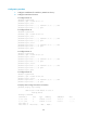
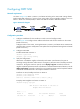
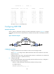
Router S, Router A, and Router D belong to the same OSPF domain as shown in Figure 32. Configure
OSPF FRR so that when the link between Router S and Router D fails, traffic is immediately switched to
Link B.
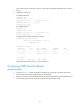
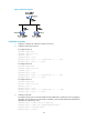
Figure 32 Network diagram
Configuration procedure
1. Configure IP addresses for the interfaces on each router and configure OSPF:
Follow Figure 32 to c
onfigure the IP address and subnet mask of each interface on the routers.
(Details not shown.)
Configure OSPF on the routers, ensuring that Router S, Router A, and Router D can communicate
with each other at Layer 3. (Details not shown.)
2. Configure OSPF FRR:
You can enable OSPF FRR to either automatically calculate a backup next hop, or designate a
backup next hop by using a routing policy.
{ Method 1: Enable OSPF FRR to automatically calculate a backup next hop.
# Configure Router S.
<RouterS> system-view
[RouterS] bfd echo-source-ip 1.1.1.1