
R3102-R3103-HP 6600/HSR6600 Routers MPLS Configuration Guide

187
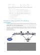
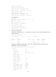
Transport Client VC Local Remote
VC ID Intf State VC Label VC Label
101 S2/1/0 up 1025 1024
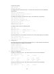
# Ping CE 2 from CE 1. The output shows that CE 1 and CE 2 can ping each other.
[CE1] ping 100.1.1.2
PING 100.1.1.2: 56 data bytes, press CTRL_C to break
Reply from 100.1.1.2: bytes=56 Sequence=1 ttl=255 time=30 ms
Reply from 100.1.1.2: bytes=56 Sequence=2 ttl=255 time=60 ms
Reply from 100.1.1.2: bytes=56 Sequence=3 ttl=255 time=50 ms
Reply from 100.1.1.2: bytes=56 Sequence=4 ttl=255 time=40 ms
Reply from 100.1.1.2: bytes=56 Sequence=5 ttl=255 time=70 ms
--- 100.1.1.2 ping statistics ---
5 packet(s) transmitted
5 packet(s) received
0.00% packet loss
round-trip min/avg/max = 30/50/70 ms
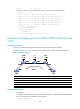
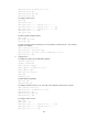
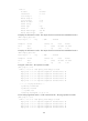
Example for configuring Martini VC redundancy
Network requirements
The CEs are connected to the PEs through serial interfaces and PPP encapsulation is used at the link layer.
Create two Martini VCs between CE 1 and CE 2, one is CE 1 – PE 1 – PE 2 – CE 2 (the primary VC) and
the other is CE 1 – PE 1 – PE 3 – CE 2 (the backup VC).
CE 1 and CE 2 communicate through the primary VC when this VC is working correctly. When PE 1
detects that the primary VC fails, it brings up the backup VC so that CE 1 and CE 2 can communicate
through the backup VC.
Figure 49 Network diagram
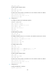
Device Interface IP address
Device
Interface
IP address
CE 1 S2
/
1
/
0 100.1.1.1/24
PE 2
Loop0
2.2.2.2/32
S2/1/0 100.2.1.1/24 sub S2/1/0 12.1.1.2/24
S2
/
1
/
1 100.3.1.1/24
PE 3
Loop0
3.3.3.3/32
PE 1 Loop0 1.1.1.1/32
S2
/
1
/
0
13.1.1.3/24
S2/1/1 12.1.1.1/24 CE 2 S2/1/0 100.1.1.2/24
S2
/
1
/
2 13.1.1.1/24
S2
/
1
/
1
100.2.1.2/24