
R3102-R3103-HP 6600/HSR6600 Routers MPLS Configuration Guide


302
MPLS L3VPN configuration examples
Configuring MPLS L3VPNs using EBGP between a PE and a CE
Network requirements
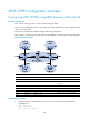
CE 1 and CE 3 belong to VPN 1. CE 2 and CE 4 belong to VPN 2.
VPN 1 uses route target attribute 111:1. VPN 2 uses route target attribute 222:2. Users of different VPNs
cannot access each other.
A PE and its connected CE use EBGP exchange VPN routing information.
PEs use OSPF to communicate with each other and use MP-IBGP to exchange VPN routing information.
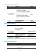
Figure 84 Network diagram
Device Interface IP address
Device
Interface
IP address
CE 1 GE 2/1/1 10.1.1.1/24
P
Loop0
2.2.2.9/32
PE 1 Loop0 1.1.1.9/32 POS 5/1/1 172.1.1.2/24
GE 2/1/1 10.1.1.2/24 POS
5/1/2/2
172.2.1.1/24
GE 2/1/2 10.2.1.2/24
PE 2
Loop0
3.3.3.9/32
POS 5/1/1 172.1.1.1/24 GE 2/1/1 10.3.1.2/24
CE 2 GE 2/1/1 10.2.1.1/24
GE 2/1/2 10.4.1.2/24
CE 3 GE 2/1/1 10.3.1.1/24
POS
5/1/1 172.2.1.2/24
CE 4 GE 2/1/1 10.4.1.1/24
Configuration procedure
1. Configure an IGP on the MPLS backbone to ensure IP connectivity within the backbone:
# Configure PE 1.
<PE1> system-view
[PE1] interface loopback 0