
R3102-R3103-HP 6600/HSR6600 Routers MPLS Configuration Guide

309
--- 10.4.1.1 ping statistics ---
5 packet(s) transmitted
0 packet(s) received
100.00% packet loss
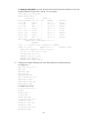
Configuring MPLS L3VPNs using IBGP between a PE and a CE
Network requirements
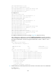
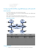
CE 1 and CE 3 belong to VPN 1. CE 2 and CE 4 belong to VPN 2.
VPN 1 uses route target attribute 111:1. VPN 2 uses route target attribute 222:2. Users of different VPNs
cannot access each other.
IBGP is used to exchange VPN routing information between CE and PE.
PEs use OSPF to communicate with each other and use MP-IBGP to exchange VPN routing information.
Figure 85 Network diagram
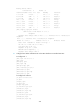
Device Interface IP address
Device
Interface
IP address
PE 1 Loop0 1.1.1.9/32 PE 2 Loop0 3.3.3.9/32
GE2/1/1 10.1.1.2/24
GE2/1/1
10.3.1.2/24
GE2/1/2 10.2.1.2/24
GE2/1/2
10.4.1.2/24
POS5/1/1 172.1.1.1/24 POS5/1/1 172.2.1.2/24
CE 1 Loop0 4.4.4.9/32
P
Loop0
2.2.2.9/32
GE2/1/1 10.1.1.1/24
POS5/1/1
172.1.1.2/24
CE 2 Loop0 5.5.5.9/32 POS5/1/2/2 172.2.1.1/24
GE2/1/1 10.2.1.1/24
CE 4
Loop0
7.7.7.9/32
CE 3 Loop0 6.6.6.9/32
GE2/1/1
10.4.1.1/24
GE2/1/1 10.3.1.1/24
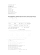
Configuration procedure
1. Configure an IGP on the MPLS backbone to ensure IP connectivity within the backbone: