
R3102-R3103-HP 6600/HSR6600 Routers MPLS Configuration Guide


422
round-trip min/avg/max = 1/1/1 ms
Configuring inter-AS IPv6 VPN option A
Network requirements
CE 1 and CE 2 belong to the same VPN. CE 1 accesses the network through PE 1 in AS 100 and CE 2
accesses the network through PE 2 in AS 200.
An inter-AS IPv6 MPLS L3VPN is implemented using option A, where the VRF-to-VRF method is used to
manage VPN routes.
The MPLS backbone in each AS runs OSPF.
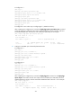
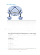
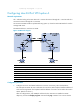
Figure 103 Network diagram
Device Interface IP address
Device
Interface IP address
CE 1 GE2/1/1 2001:1::1/96 CE 2 GE2/1/1 2001:2::1/96
PE 1 Loop0 1.1.1.9/32
PE 2
Loop0 4.4.4.9/32
GE2/1/1 2001:1::2/96
GE2/1/1 2001:2::2/96
POS5/1/1 172.1.1.2/24 POS5/1/1 162.1.1.2/24
A
SBR-PE1 Loop0 2.2.2.9/32
A
SBR-PE2
Loop0 3.3.3.9/32
POS5/1/1 172.1.1.1/24
POS5/1/1 162.1.1.1/24
POS5/1/2 2002:1::1/96 POS5/1/2 2002:1::2/96
Configuration procedure
1. Configure an IGP on each MPLS backbone to ensure IP connectivity within the backbone:
This example uses OSPF. Be sure to advertise the route to the 32-bit loopback interface address of
each router through OSPF. The loopback interface address of a router is to be used as the router's
LSR ID. (Details not shown.)
After the configurations, each ASBR PE and the PE in the same AS can establish an OSPF
adjacency. Execute the display ospf peer command and ping command. You can see that the