
R3303-HP 6600/HSR6600 Routers Layer 3 - IP Routing Configuration Guide

249
*>i 8.1.1.0/24 3.1.1.2 0 100 0 65008i
* i 9.1.1.0/24 2.2.2.2 0 100 0 ?
The output shows that the route 8.1.1.0 becomes valid with the next hop as Router A.
5. Verify the configuration:
# Ping 8.1.1.1 on Router C.
[RouterC] ping 8.1.1.1
PING 8.1.1.1: 56 data bytes, press CTRL_C to break
Reply from 8.1.1.1: bytes=56 Sequence=1 ttl=254 time=2 ms
Reply from 8.1.1.1: bytes=56 Sequence=2 ttl=254 time=2 ms
Reply from 8.1.1.1: bytes=56 Sequence=3 ttl=254 time=2 ms
Reply from 8.1.1.1: bytes=56 Sequence=4 ttl=254 time=2 ms
Reply from 8.1.1.1: bytes=56 Sequence=5 ttl=254 time=2 ms
--- 8.1.1.1 ping statistics ---
5 packet(s) transmitted
5 packet(s) received
0.00% packet loss
round-trip min/avg/max = 2/2/2 ms
BGP and IGP synchronization configuration
Network requirements
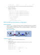
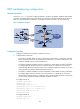
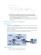
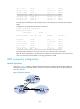
As shown in Figure 74, all devices of company A reside in AS 65008 while all devices of company B
reside in AS 65009. AS 65008 and AS 65009 are connected through Router A and Router B. It is
required that Router A can access network 9.1.2.0/24 in AS 65009, and Router C can access network
8.1.1.0/24 in AS 65008.
Figure 74 Network diagram
Configuration procedure
1. Configure IP addresses for interfaces. (Details not shown.)
2. Configure OSPF:
Enable OSPF in AS 65009, so that Router B can obtain the route to 9.1.2.0/24.
# Configure Router B.
<RouterB> system-view
[RouterB] ospf 1
[RouterB-ospf-1] area 0
[RouterB-ospf-1-area-0.0.0.0] network 2.2.2.2 0.0.0.0
[RouterB-ospf-1-area-0.0.0.0] network 9.1.1.0 0.0.0.255
[RouterB-ospf-1-area-0.0.0.0] quit
Router A
AS 65008
S2/2/1
3.1.1.1/24
Router CRouter B
AS 65009
GE2/1/1
8.1.1.1/24
S2/2/1
3.1.1.2/24
S2/2/0
9.1.1.1/24
S2/2/0
9.1.1.2/24
Loop0
1.1.1.1/32
Loop0
2.2.2.2/32
Loop0
3.3.3.3/32
EBGP OSPF
GE2/1/1
9.1.2.1/24