
R3303-HP 6600/HSR6600 Routers MPLS Configuration Guide
178
[CE1-Serial2/1/0] ip address 100.1.1.1 24
2. Configure the PE:
# Configure the LSR ID and enable MPLS globally.
<Sysname> system-view
[Sysname] sysname PE
[PE] interface loopback 0
[PE-LoopBack0] ip address 172.1.1.1 32
[PE-LoopBack0] quit
[PE] mpls lsr-id 172.1.1.1
[PE] mpls
[PE-mpls] quit
# Enable L2VPN and MPLS L2VPN.
[PE] l2vpn
[PE-l2vpn] mpls l2vpn
[PE-l2vpn] quit
# Configure the link protocol type of interface Serial 2/1/0 as PPP.
[PE] interface serial 2/1/0
[PE-Serial2/1/0] link-protocol ppp
[PE-Serial2/1/0] quit
# Configure the link protocol type of interface Serial 2/1/1 as PPP.
[PE] interface serial 2/1/1
[PE-Serial2/1/1] link-protocol ppp
[PE-Serial2/1/1] quit
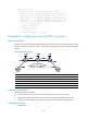
# Create a local connection between CE 1 and CE 2.
[PE] ccc ce1-ce2 interface serial 2/1/0 out-interface serial 2/1/1
3. Configure CE 2:
# Configure the link protocol type of interface Serial 2/1/0 (the interface connected to the PE) as
PPP, and configure an IP address for the interface.
<Sysname> system-view
[Sysname] sysname CE2
[CE2] interface serial 2/1/0
[CE2-Serial2/1/0] link-protocol ppp
[CE2-Serial2/1/0] ip address 100.1.1.2 24
Verifying the configuration:
# Execute the display ccc command on the PE to display CCC connection information. The output
shows that a local CCC connection has been established.
[PE] display ccc
Total ccc vc : 1
Local ccc vc : 1, 1 up
Remote ccc vc : 0, 0 up
***Name : ce1-ce2
Type : local
State : up
Intf1 : Serial2/1/0 (up)
Intf2 : Serial2/1/1 (up)
# Ping CE 2 from CE 1. The output shows that CE 1 and CE 2 can ping each other.