
R3303-HP 6600/HSR6600 Routers MPLS Configuration Guide


231
Configuring H-VPLS with LSP access
Network requirements
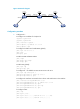
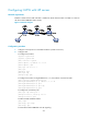
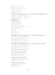
Establish a U-PW between UPE and NPE 1. Establish an N-PW between NPE 1 and NPE 3. Create an
LDP VPLS instance aaa (the Martini mode).
Figure 61 Network diagram
Configuration procedure
1. Configure an IGP protocol on the MPLS backbone. (Details not shown.)
2. Configure UPE:
# Configure basic MPLS.
<Sysname> system-view
[Sysname] sysname UPE
[UPE] interface loopback 0
[UPE-LoopBack0] ip address 1.1.1.9 32
[UPE-LoopBack0] quit
[UPE] mpls lsr-id 1.1.1.9
[UPE] mpls
[UPE-mpls] quit
[UPE] mpls ldp
[UPE-mpls-ldp] quit
# Configure basic MPLS on GigabitEthernet 2/1/2, the interface connected to NPE 1.
[UPE] interface gigabitethernet 2/1/2
[UPE-GigabitEthernet2/1/2] ip address 10.1.1.1 24
[UPE-GigabitEthernet2/1/2] mpls
[UPE-GigabitEthernet2/1/2] mpls ldp
[UPE-GigabitEthernet2/1/2] quit
# Configure the remote LDP peer.
[UPE] mpls ldp remote-peer 1
[UPE-mpls-remote-1] remote-ip 2.2.2.9
[UPE-mpls-remote-1] quit
# Enable L2VPN and MPLS L2VPN.
[UPE] l2vpn
[UPE-l2vpn] mpls l2vpn
[UPE-l2vpn] quit
# Create VPLS instance aaa that uses LDP signaling.