
R3303-HP 6600/HSR6600 Routers Security Configuration Guide

160
Configuring portal stateful failover(6600/HSR6600)
Network requirements
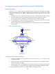
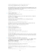
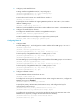
As shown in Figure 62, a failover link is present between Router A and Router B. Both Router A and Router
B support portal authentication. Configure stateful failover between Router A and Router B to support
portal service backup and use VRRP to implement traffic switchover between the routers. More
specifically,
• When Router A works normally, Host accesses Router A for portal authentication before accessing
the Internet. When Router A fails, Host accesses the Internet through Router B. The VRRP
uplink/downlink detection mechanism is used to ensure non-stop traffic forwarding.
• Use the RADIUS server as the authentication/authorization server. In this example, Server takes the
responsibilities of the portal server and the RADIUS server.
• Router A and Router B use a dedicated physical link as the failover link to transmit stateful failover
related packets.
Figure 62 Network diagram
Configuration prerequisites and guidelines
• Configure IP addresses for the host, server, and routers as shown in Figure 62 and make sure they
can reach each other.
• Make sure the host can access the authentication server through Router A and Router B before
portal authentication is enabled.
• Configure VRRP group 1 and VRRP group 2 to implement backup for downstream and upstream
links respectively. For more information about VRRP, see High Availability Configuration Guide.
For information about stateful failover, see High Availability Configuration Guide.
Router A
Backup link
Host
9.9.1.2/24
Gateway: 9.9.1.1/24
Router B
GE0/0/1
9.9.1.5/24
GE0/0/1
9.9.1.6/24
GE0/0/2
192.168.0.6/24
GE0/0/2
192.168.0.5/24
GE0/0/3
GE0/0/3
Virtual IP address 2:
192.168.0.1/24
Server
Master Backup
Virtual IP address 1:
9.9.1.1/24
Master
Backup
L2 Switch
L2 Switch
IP: 192.168.0.111/24
Gateway: 192.168.0.1/24