
R3303-HP 6600/HSR6600 Routers Security Configuration Guide

516
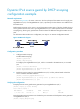
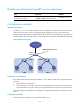
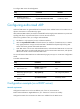
Figure 249 Network diagram
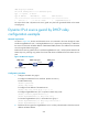
Configuration procedure
1. Configure Router A:
# Configure the IP address of GigabitEthernet 3/0/1.
<RouterA> system-view
[RouterA] interface gigabitethernet 3/0/1
[RouterA-GigabitEthernet3/0/1] ip address 10.1.1.1 24
[RouterA-GigabitEthernet3/0/1] quit
# Configure DHCP.
[RouterA] dhcp enable
[RouterA] dhcp server ip-pool 1
[RouterA-dhcp-pool-1] network 10.1.1.0 mask 255.255.255.0
[RouterA-dhcp-pool-1] quit
# Enter Layer 3 Ethernet interface view.
[RouterA] interface gigabitethernet 3/0/1
# Configure the DHCP server to support authorized ARP.
[RouterA-GigabitEthernet3/0/1] dhcp update arp
# Enable authorized ARP.
[RouterA-GigabitEthernet3/0/1] arp authorized enable
[RouterA-GigabitEthernet3/0/1] quit
2. Configure Router B:
<RouterB> system-view
[RouterB] interface gigabitethernet 3/0/1
[RouterB-GigabitEthernet3/0/1] ip address dhcp-alloc
[RouterB-GigabitEthernet3/0/1] quit
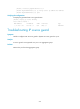
3. After Router B obtains an IP address from Router A, display the authorized ARP entry information
on Router A.
[RouterA] display arp all
Type: S-Static D-Dynamic A-Authorized
IP Address MAC Address VLAN ID Interface Aging Type
10.1.1.2 0012-3f86-e94c N/A GE3/0/1 N/A A
The output shows that an IP address 10.1.1.2 has been assigned to Router B.
Router B must use the IP address and MAC address in the authorized ARP entry to communicate
with Router A. Otherwise, the communication fails. Thus user validity is ensured.