
R3102-R3103-HP 6600/HSR6600 Routers High Availability Configuration Guide
106
[RouterH-GigabitEthernet3/0/1] undo stp enable
[RouterH-GigabitEthernet3/0/1] port link-type trunk
[RouterH-GigabitEthernet3/0/1] port trunk permit vlan 1 to 30
[RouterH-GigabitEthernet3/0/1] quit
[RouterH] interface gigabitethernet 3/0/2
[RouterH-GigabitEthernet3/0/2] link-delay 0
[RouterH-GigabitEthernet3/0/2] undo stp enable
[RouterH-GigabitEthernet3/0/2] port link-type trunk
[RouterH-GigabitEthernet3/0/2] port trunk permit vlan 1 to 30
[RouterH-GigabitEthernet3/0/2] quit
# Create RRPP domain 1, configure VLAN 4092 as the primary control VLAN of RRPP domain 1,
and configure the VLANs mapped to MSTI 1 as the protected VLANs of RRPP domain 1.
[RouterH] rrpp domain 1
[RouterH-rrpp-domain1] control-vlan 4092
[RouterH-rrpp-domain1] protected-vlan reference-instance 1
# Configure Router H as the master node of subring 5, with GigabitEthernet 3/0/1 as the
primary port and GigabitEthernet 3/0/2 as the secondary port, and enable subring 5.
[RouterH-rrpp-domain1] ring 5 node-mode master primary-port gigabitethernet 3/0/1
secondary-port gigabitethernet 3/0/2 level 1
[RouterH-rrpp-domain1] ring 5 enable
[RouterH-rrpp-domain1] quit
# Enable RRPP.
[RouterH] rrpp enable
9. Verify the configuration:
Use the display command to view RRPP configuration and operational information on each
device.
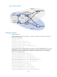
Load balanced intersecting-ring configuration example
Networking requirements
As shown in Figure 27,
Router A, Router B, Router C, Router D, and Router F form RRPP domain 1, and VLAN 100 is the
primary control VLAN of the RRPP domain. Router A is the master node of the primary ring, Ring
1. Router D is the transit node of Ring 1. Router F is the master node of the subring Ring 3.
Router C is the edge node of the subring Ring 3. Router B is the assistant-edge node of the
subring Ring 3.
Router A, Router B, Router C, Router D, and Router E form RRPP domain 2, and VLAN 105 is the
primary control VLAN of the RRPP domain. Router A is the master node of the primary ring, Ring
1. Router D is the transit node of Ring 1. Router E is the master node of the subring Ring 2.
Router C is the edge node of the subring Ring 2. Router B is the assistant-edge node of the
subring Ring 2.
Specify VLAN 11 as the protected VLAN of domain 1, and VLAN 12 the protected VLAN of
domain 2. You can implement VLAN-based load balancing on Ring 1.
Because Ring 2 has the same edge node and assistant-edge node, and the two subrings have
the same SRPTs, you can add Ring 2 and Ring 3 to the RRPP ring group to reduce Edge-Hello
traffic.