
R3102-R3103-HP 6600/HSR6600 Routers High Availability Configuration Guide

121
NOTE:
A loop might occur on the network during the time when the spanning tree feature is disabled but Smart
Link has not yet taken effect on a port.
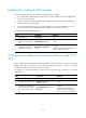
Configuring protected VLANs for a smart link group
You can configure protected VLANs for a smart link group by referencing MSTIs. Before configuring
the protected VLANs, configure the mappings between MSTIs and the VLANs to be protected (a
device working in PVST mode automatically maps VLANs to MSTIs). For more information about
MSTIs and PVST, see Layer 2—LAN Switching Configuration Guide.
To configure the protected VLANs for a smart link group:
Step
Command
Remarks
1. Enter system view.
system-view
N/A
2. Enter MST region view.
stp region-configuration
Not required if the device is
operating in PVST mode.
For more information about the
command, see Layer 2—LAN
Switching Command Reference.
3. Configure the
VLAN-to-instance mapping
table.
Method 1:
instance instance-id vlan
vlan-list
Method 2:
vlan-mapping modulo
modulo
Optional.
Use either method.
All VLANs in an MST region are
mapped to CIST (MSTI 0) by
default.
Not required if the device is
operating in PVST mode.
For more information about the
commands, see Layer 2—LAN
Switching Command Reference.
4. Activate MST region
configuration manually.
active region-configuration
Not required if the device is
operating in PVST mode.
For more information about the
command, see Layer 2—LAN
Switching Command Reference.
5. Display the currently
activated configuration
information of the MST
region.
display stp region-configuration
[ | { begin | exclude | include }
regular-expression ]
Optional.
Available in any view.
The output of the command includes
VLAN-to-instance mappings.
For more information about the
command, see Layer 2—LAN
Switching Command Reference.
6. Return to system view.
quit
Not required if the device is
operating in PVST mode.
7. Create a smart link group
and enter smart link group
view.
smart-link group group-id
N/A