
R3102-R3103-HP 6600/HSR6600 Routers High Availability Configuration Guide


125
Smart Link configuration examples
Single smart link group configuration example
Network requirements
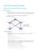
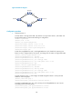
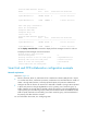
As shown in Figure 29:
Router C and Router D are Smart Link devices. Router A, Router B, and Router E are associated
devices. Traffic of VLANs 1 through 30 on Router C and Router D are dually uplinked to Router
A.
Configure Smart Link on Router C and Router D for dual uplink backup.
Figure 29 Network diagram
Configuration procedure
1. Configure Router C:
# Create VLANs 1 through 30, map these VLANs to MSTI 1, and activate the MST region
configuration.
<RouterC> system-view
[RouterC] vlan 1 to 30
[RouterC] stp region-configuration
[RouterC-mst-region] instance 1 vlan 1 to 30
[RouterC-mst-region] active region-configuration
[RouterC-mst-region] quit
# Shut down GigabitEthernet 3/0/1 and GigabitEthernet 3/0/2, disable the spanning tree
feature on GigabitEthernet 3/0/1 and GigabitEthernet 3/0/2 separately, configure them as
trunk ports, and assign them to VLANs 1 through 30.
[RouterC] interface gigabitethernet 3/0/1
[RouterC-GigabitEthernet3/0/1] shutdown
[RouterC-GigabitEthernet3/0/1] undo stp enable
[RouterC-GigabitEthernet3/0/1] port link-type trunk
[RouterC-GigabitEthernet3/0/1] port trunk permit vlan 1 to 30
Router A
Router E
Router DRouter C
Router B
GE
3
/0
/
1
GE
3
/
0
/2
GE
3
/
0
/
1
GE
3
/
0
/
1
GE
3
/
0
/
2
GE
3
/0
/2
GE3/0/3
GE3/0/1
GE3/0/2
GE3/0/3
GE3/0/1
GE3/0/2
Master link
Slave link
Smart link group