
R3102-R3103-HP 6600/HSR6600 Routers High Availability Configuration Guide

134
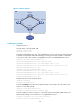
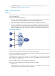
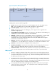
Figure 31 Network diagram
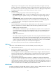
Configuration procedure
1. Configure Router A:
# Create VLAN 1 through VLAN 200.
<RouterA> system-view
[RouterA] vlan 1 to 200
# Configure GigabitEthernet 3/0/1 and GigabitEthernet 3/0/2 as trunk ports and assign them
to VLANs 1 through 200. Enable flush message receiving and configure VLAN 10 and VLAN
110 as the receive control VLANs on GigabitEthernet 3/0/1 and GigabitEthernet 3/0/2.
[RouterA] interface gigabitethernet 3/0/1
[RouterA-GigabitEthernet3/0/1] port link-type trunk
[RouterA-GigabitEthernet3/0/1] port trunk permit vlan 1 to 200
[RouterA-GigabitEthernet3/0/1] smart-link flush enable control-vlan 10 110
[RouterA-GigabitEthernet3/0/1] quit
[RouterA] interface gigabitethernet 3/0/2
[RouterA-GigabitEthernet3/0/2] port link-type trunk
[RouterA-GigabitEthernet3/0/2] port trunk permit vlan 1 to 200
[RouterA-GigabitEthernet3/0/2] smart-link flush enable control-vlan 10 110
[RouterA-GigabitEthernet3/0/2] quit
# Enable CFD and create an MD of level 5.
[RouterA] cfd enable
[RouterA] cfd md MD level 5
# Create MA MA_A for the MD and configure the MA to serve VLAN 10, and create service
instance 1 for the MD and MA.
[RouterA] cfd ma MA_A md MD vlan 10
[RouterA] cfd service-instance 1 md MD ma MA_A
# Create a MEP list in service instance 1, create and enable outward-facing MEP 1002, and
enable CCM sending in service instance 1 on GigabitEthernet 3/0/1.
[RouterA] cfd meplist 1001 1002 service-instance 1
[RouterA] interface gigabitethernet 3/0/1
Router A
Router DRouter B
GE
3
/0
/
1
GE
3
/
0
/2
GE
3
/
0
/
1
GE
3
/
0
/
1
GE
3
/
0
/
2
GE
3
/
0
/
2
Router C
GE3
/
0
/
1
GE
3
/
0
/
2
MD
Outward-facing MEP
User network