
R3102-R3103-HP 6600/HSR6600 Routers High Availability Configuration Guide


175
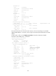
The output shows that in VRRP group 1 Router A is the master, Router B is the backup and the
host with the default gateway of 202.38.160.111/24 accesses the Internet through Router A. In
VRRP group 2 Router A is the backup, Router B is the master and the host with the default
gateway of 202.38.160.112/24 accesses the Internet through Router B.
NOTE:
To implement load balancing between the VRRP groups, be sure to configure the default gateway as
202.38.160.111 or 202.38.160.112 on the hosts on network segment 202.38.160.0/24.
VRRP load balancing mode configuration example
Network requirements
Router A, Router B, and Router C belong to VRRP group 1 with the virtual IP address of
10.1.1.1/24.
Hosts on network segment 10.1.1.0/24 use 10.1.1.1/24 as their default gateway. Use the
VRRP group to make sure that when a gateway (Router A, Router B, or Router C) fails, the hosts
on the LAN can access the external network through another gateway.
VRRP group 1 operates in load balancing mode to make good use of network resources.
Configure a track entry on Router A, Router B, and Router C to monitor their own
GigabitEthernet 1/0/2. When the interface on Router A, Router B, or Router C fails, the weight
of the corresponding router decreases so that another router with a higher weight can take over.
Configure track entries on Router C to monitor Router A and Router B. When Router A or Router
B fails, Router C immediately takes over the AVF on Router A or Router B.
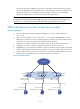
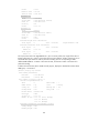
Figure 47 Network diagram
Host A Host B Host C
Router A Router B Router C
GE1/0/1
IP: 10.1.1.2/24
VIP: 10.1.1.1/24
Network
GE1/0/1
IP: 10.1.1.3/24
VIP: 10.1.1.1/24
GE1/0/1
IP: 10.1.1.4/24
VIP: 10.1.1.1/24
Master
AVF 1
Backup
AVF 2
Backup
AVF 3
IP: 10.1.1.5/24
Gateway IP: 10.1.1.1/24
IP: 10.1.1.6/24
Gateway IP: 10.1.1.1/24
IP: 10.1.1.7/24
Gateway IP: 10.1.1.1/24
GE1/0/2 GE1/0/2
GE1/0/2