
R3102-R3103-HP 6600/HSR6600 Routers Interface Configuration Guide


51
[RouterB-Pos2/1/0] mtu 1500
[RouterB-Pos2/1/0] shutdown
[RouterB-Pos2/1/0] undo shutdown
Verifying the configuration
Check the interface connectivity between the POS interfaces with the display interface pos
command and test network connectivity with the ping command.
Connecting routers through POS interfaces across frame relay
Network requirements
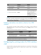
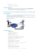
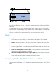
As shown in Figure 5, connect routers to a public frame relay network through POS interfaces. The routers
are premise equipment that work as DTE side of frame relay.
Router A uses frame relay sub-interfaces to connect Router B and Router C in different network segments.
Figure 5 Network diagram
Configuration procedure
1. Configure Router A:
# Configure POS interface 2/1/0.
<RouterA> system-view
[RouterA] interface pos 2/1/0
[RouterA-Pos2/1/0] clock slave
# Configure frame relay encapsulation on the interface.
[RouterA-Pos2/1/0] link-protocol fr
[RouterA-Pos2/1/0] fr interface-type dte
[RouterA-Pos2/1/0] quit
# Create sub-interface 1 on the interface.
[RouterA] interface pos 2/1/0.1
[RouterA-Pos2/1/0.1] ip address 10.10.10.1 255.255.255.0
[RouterA-Pos2/1/0.1] fr map ip 10.10.10.2 50
[RouterA-Pos2/1/0.1] mtu 1500
[RouterA-Pos2/1/0.1] quit
# Create sub-interface 2 on the interface.
[RouterA] interface pos 2/1/0.2
[RouterA-Pos2/1/0.2] ip address 20.10.10.1 255.255.255.0